


The Frequency Conversion automatic feeder utilizes the gravity of the process medium, serving two purposes with one pump. When the medium gravity is used in conjunction with the centrifugal pump, it realizes the bidirectional flow of the process medium in both forward and reverse directions. The steam condensate from the brine heater and the feed evaporation system enters the recovery water tank. The liquid level in the recovery water tank rises, the automatic regulating valve closes, and the steam condensate is sent to the condensate storage tank for storage through the return pipe of the centrifugal pump. The liquid level in the condensate storage tank rises.

 020-34563445
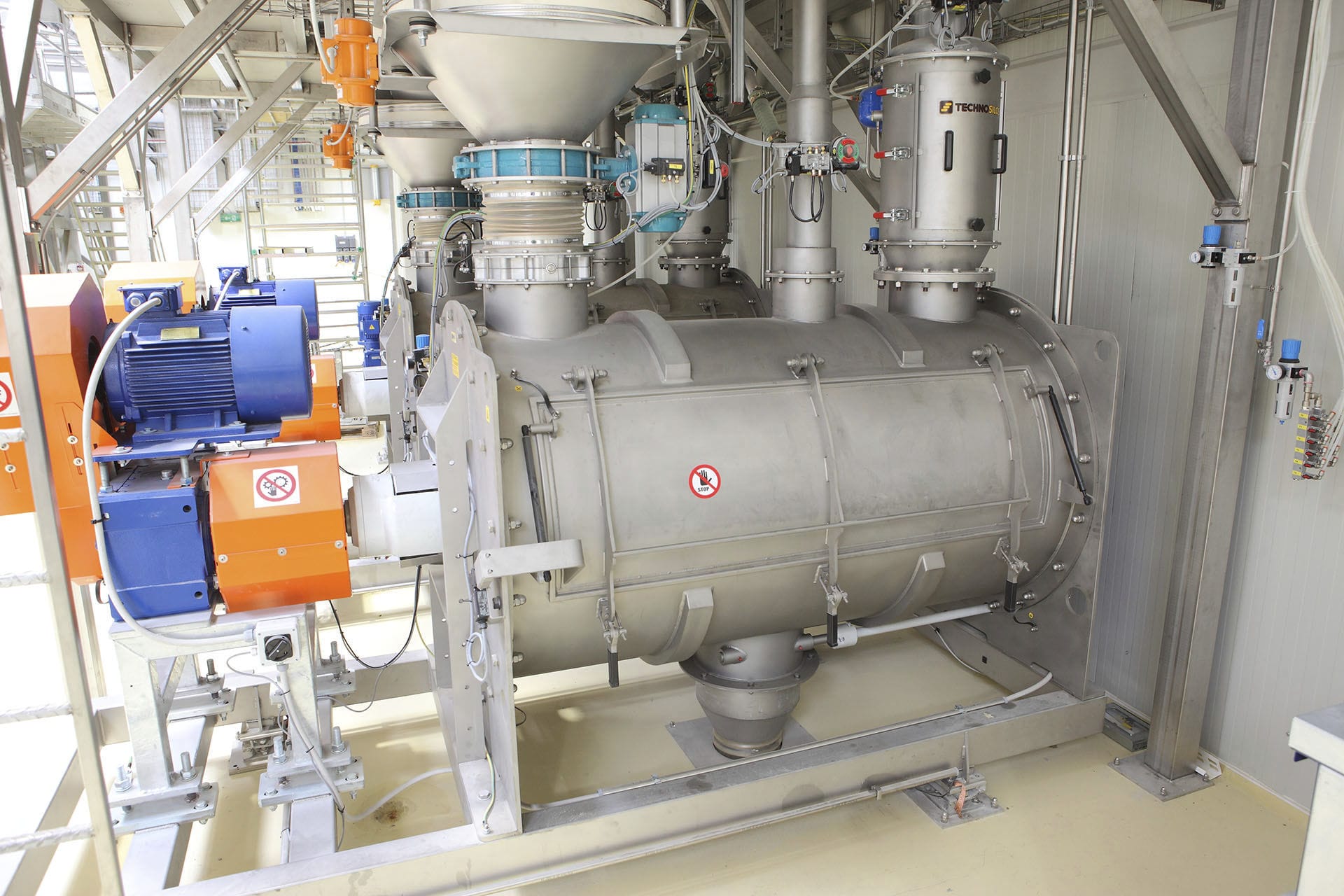
The variable-frequency automatic Feeder operates according to the production scheduling instructions on the raw material output volume. After determining the feeding volume, other materials are automatically adjusted proportionally based on the pre-set feeding volume in the system. The writing of system formula data and start-stop commands are all completed by the main control room DCS system, which also monitors the batching process and processes relevant data. The main control DCS system transmits the data to the on-site PLC for the start-stop and speed adjustment of the feeder, achieving automatic batching and achieving the dual effects of diversion and reflux, achieving the purpose of controlling the liquid level of 2 pieces of equipment with 1 automatic regulating valve, using the gravity of the process medium, one pump for two uses, the medium gravity and centrifugal pump are used together to achieve the bidirectional flow of the process medium. The steam condensate from the feed heater and the feed evaporation system enters the recovery water material tank, the liquid level of the recovery water material tank rises, the automatic regulating valve closes, the steam condensate is sent by the centrifugal pump return pipe to the condensate storage tank for storage, and the liquid level of the condensate storage tank rises.
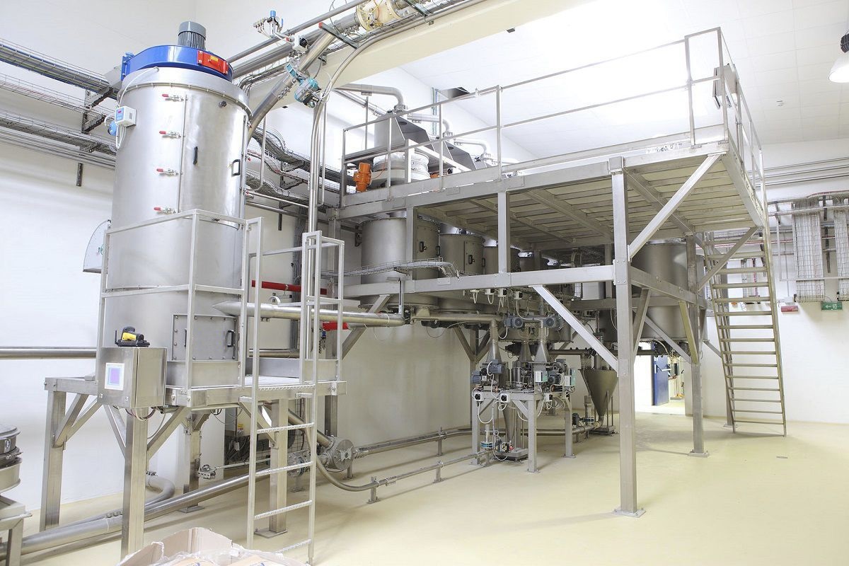
The feeder places the material tank in the pit as the recovery water material tank, the steam hot water generated by the feed heater and the feed evaporation system is introduced into the water material tank through the pipeline. After disconnecting the finished material tank area high-concentration material tank from the feeding system and using it as a hot water storage tank, the material tank is connected to the water material tank through buried pipes. The material pump is used as a centrifugal pump to send the hot water to the first feed auxiliary material preparation position, the pump return pipe is connected to the buried pipe of the hot water storage tank and the recovery water material tank, and the section of the pipeline from the connection point to the recovery water material tank is called the dual-loop recovery main pipe. After the remote transmission liquid level meter of the material tank is shifted, it still serves as the remote transmission liquid level meter of the recovery water material tank, the original pump outlet D50 automatic regulating valve is replaced by D80 automatic regulating valve, and the installation position is modified to the dual-loop control main pipe, and it is linked with the remote transmission liquid level meter of the recovery water material tank for chain control.
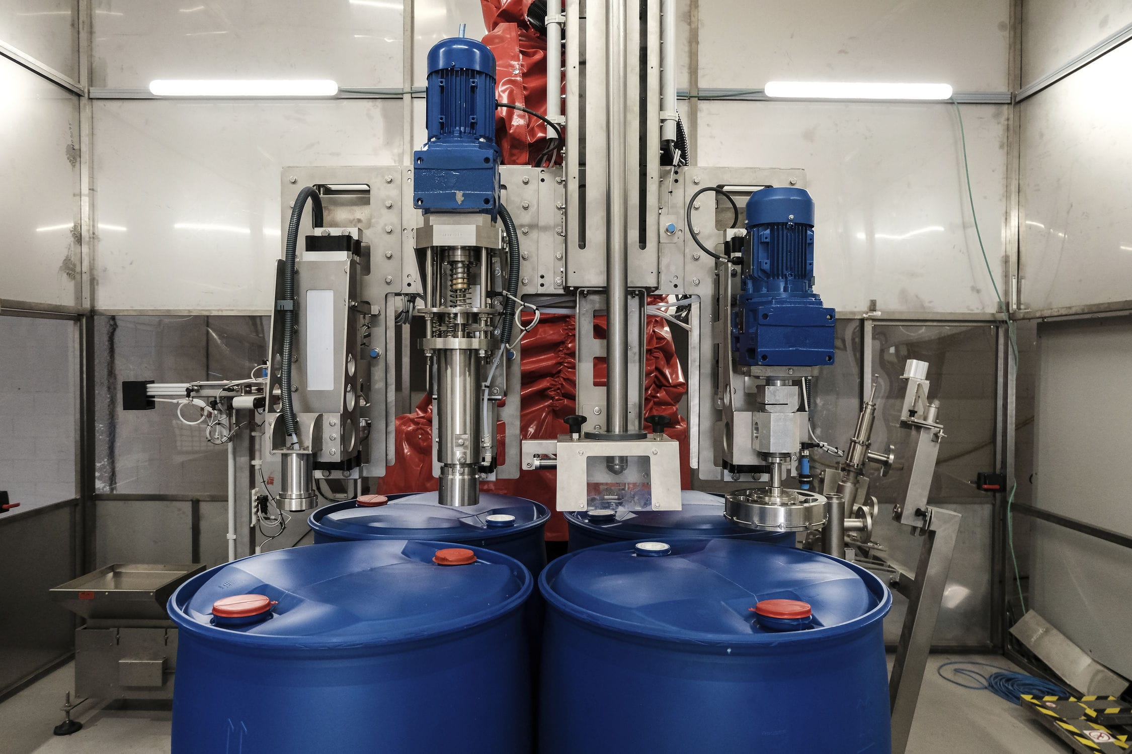
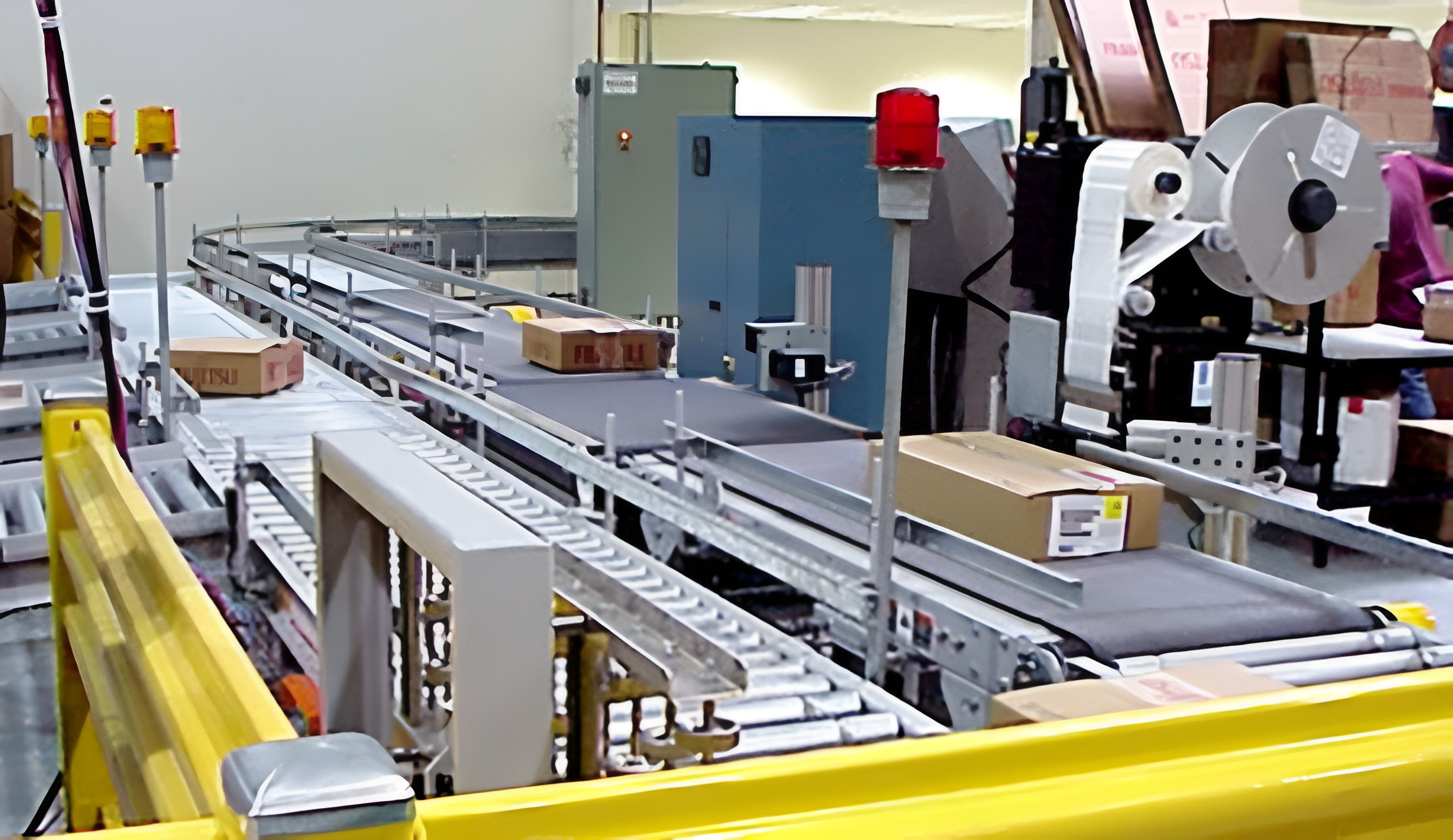
The feeder realizes the full automatic control and management of the liquid feeding system for pigs, using an electrical control system composed of a computer, PLC control system, weighing module, and solenoid valve, and completing the software design of the system. Through the computer software, the management of livestock records is realized, and the PLC communication provides feeding information and parameters to the PLC control system, and the PC controls the weighing module to sample and program control the solenoid valve to achieve feeding. When the feeding system is working, the operator inputs feeding information (including feeding time, feeding pig house number, feed number, feed quality, ratio concentration, etc.) and system parameters from the upper computer, forming an information queue, which is conveyed to the lower computer PLC for reception through the communication block. After the lower computer starts initialization, it waits for the command from the upper computer. Reading one piece of information from the queue is assigned to the making material tank, the water pump is started, the ring-shaped pipeline and the required feeding pig house pipeline are connected to supply water to the making material tank, the weighing module of the making material tank weighs and then opens the corresponding feed valve, and the feed is poured into the making material tank through the belt transmission and buffer device, and is weighed by the weighing module in the making material tank. When it reaches the specified value, the feed valve is closed. The stirring motor in the making material tank is started to stir for a specified time until it is uniform. The feeding pump is started through the ring-shaped distributor to supply feed to the pig house. During feeding, the valves of the pig pen are opened one by one, and when the weighing module weighs the mass of the making material tank, it is the amount of feed to the corresponding pig pen. After one feeding session, the making material tank determines whether there are still messages in the message queue and repeats the above process.
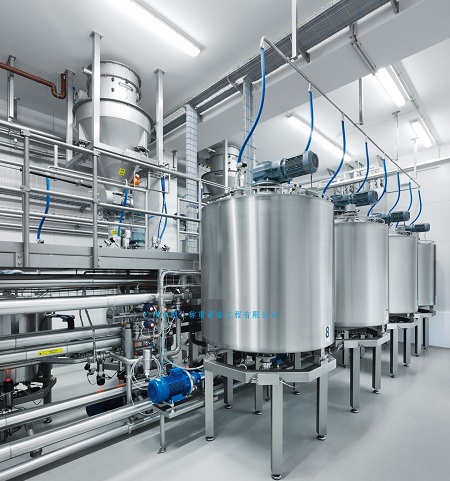
The feeder consists of a feeding structure, a liquid feed mixing and stirring structure, a feeding system and pipelines, pig house pipelines, electrical control system, and upper computer control system. The feeding structure places various feeds in the material tank, and the system contains multiple material tanks. The material tanks are equipped with solenoid valves, and by opening the solenoid valve under the material tank, the feed enters the transmission belt and slowly descends to the making material tank for stirring; the mixing and stirring structure is equipped with a stirring motor and weighing module in each making material tank, and the sensor signals will enter the analog input module of the PLC; The feeding system is mainly composed of temporary storage tanks, relays, and ring-shaped distributors, etc. Among them, the temporary storage tanks are equipped with Weighing modules. The pigsty pipelines have a feeding trough in each pigsty, and the solenoid valve controls whether the pipeline supplies feed to the trough. The electrical control part uses the widely used PLC in the industry as the control core, and consists of a main control cabinet and two slave control cabinets, combined with corresponding software, weighing modules, and corresponding executive components to automatically control the entire feeding operation process; the upper computer control part mainly provides a human-computer interaction interface on the server and realizes the communication between the upper and lower PLCs.


