


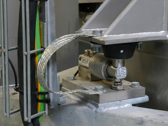


The weight verification instrument without weights is fixedly connected to the supporting beam or the foundation through welding or bolts on the gantry frame. The center position of the horizontal crossbeam of the gantry frame is equipped with a jack, which is vertically and perpendicularly set on the upper surface of the standard weighing module used for calibration. The lower part of the standard weighing module for calibration is the pressure platform. Between the gantry frame and the jack, a certain thickness of spacer blocks are set. The weighing instrument is configured with each standard weighing module and is placed outside for easy observation of the results. The number of the calibration device's enclosures is corresponding to the number of the calibrated weighing modules used in the on-site hopper weighing design.

 020-34563445
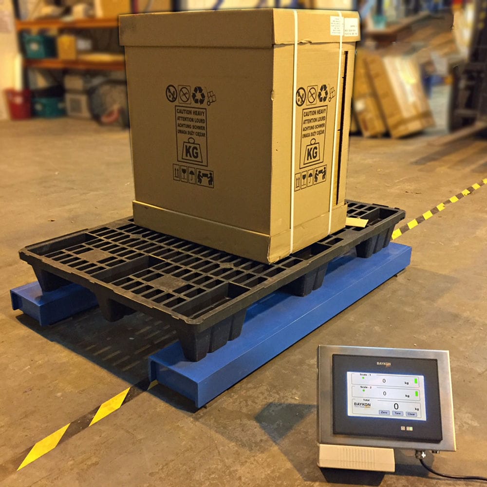
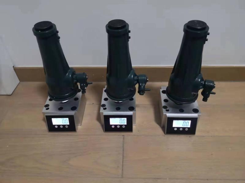
The weighing calibration instrument is composed of a weighing module, a high-precision portable weighing force-measuring instrument, and a manual hydraulic loading jack mechanism. According to the principle of the superimposed force-measuring machine, by comparing the output data of the weighing module and the force-measuring device, it determines whether the inspected equipment is normal. It is applicable in situations where the force-measuring device is restricted by space and for the calibration of hopper scales. The measurement channels 1 to 4 can be selected, with an accuracy level of 0.1 grade. The single sensor starts the traceability from 10% of the measurement, and the combined sensor starts the traceability from 20%. The display instrument is a 7-inch color touch screen that displays the measurement data of each channel and the total of the data. It has the functions of de-weighting/clearing zero, overload alarm, multi-point linear correction. It adopts an imported hydraulic control system and a one-to-four pressure reduction system to ensure that the same force is simultaneously applied and unloaded at multiple force-receiving points.
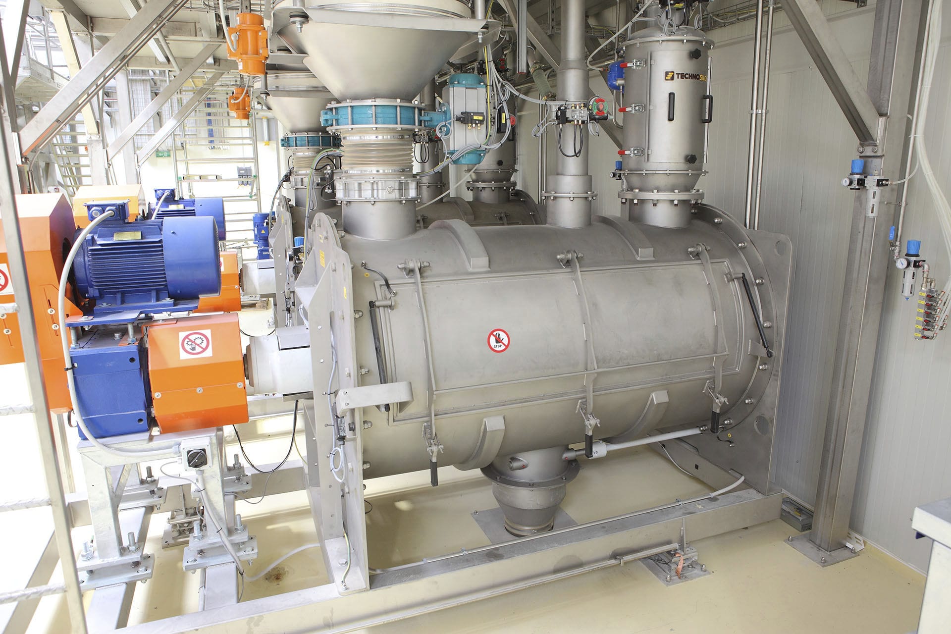
The hopper scale is composed of a weighing hopper, a weighing module, a weighing connection box, and a weighing instrument. The weighing hopper is used to hold the material to be weighed and transfer its weight to multiple Weighing modules located between the weighing hopper and the foundation. The elastic body inside the sensor deforms due to the force, and the resistance value of the internal chip changes. Under the bridge voltage, it outputs a voltage signal proportional to the weight of the weighed material. This voltage signal is transmitted through the weighing connection box via a shielded cable to the corresponding weighing instrument or weighing module. The voltage signal is amplified and converted by the internal amplification and conversion circuit of the weighing instrument into the corresponding weight (or material height, i.e., material level) display value. At the same time, the weighing instrument outputs a 4-20mADC standard current signal corresponding to the display value to the PLC or other control units to achieve automatic control of the Weighing system. The calibration device for the hopper scale with horizontal detection of the hopper scale is fixedly connected to the support beam by welding or bolts to the supporting beam or the foundation. The horizontal crossbeam of the support beam is provided with a jack at the center position at the lower end, and the vertical jack is set perpendicularly on the upper surface of the standard weighing module used for calibration. The lower part of the calibration standard weighing module is the pressure platform, and a certain thickness of spacer is set between the support beam and the jack. The horizontal levels are connected by the connecting hoses of the horizontal level group to form a closed serial connection. The pressure platform is set on the outer side of each side of the hopper, and each support arm extends horizontally towards the outer side of each side. The weighing instrument is configured with each standard weighing module and is placed outside a place convenient for observing the results. The number of calibration devices corresponds to the number of the calibrated weighing modules used in the on-site hopper scale design.
Before calibrating the hopper scale, first place the horizontal level group composed of 4 horizontal levels on the horizontal plane of the weighing hopper/warehouse, and distribute them evenly at the four corners of the horizontal plane. Use a funnel and a medical syringe to inject an appropriate amount of water through a plastic tube with a scale on the upper end into the horizontal level group. By detecting the actual scale reading of the water in each horizontal level, check whether the installation of the weighing hopper/warehouse is level. If not level, make necessary adjustments until it reaches a level state. Then remove all the magnetic horizontal levels from the weighing hopper and calibrate the Electronic scale to zero. After completing the zero calibration, place the horizontal levels back on the weighing hopper, and place the horizontal level group on the horizontal plane of the weighing hopper or stick them at the same horizontal height on the side of the weighing hopper at the same position for easy real-time observation during loading. Then prepare for loading calibration.
During the loading process, apply a force upward to the support beam through the jack, and rely on the downward reaction force formed by the support beam. This force is simultaneously applied to the standard weighing module and the calibrated weighing module, and is accurately displayed by the standard electronic scale composed of the standard weighing module and the weighing instrument, showing the magnitude of the force applied by each jack and the total force applied by all jacks. By operating the various buttons on the operation panel of the weighing instrument, the parameters of the central control unit inside the weighing instrument can be set. The display screen of the weighing instrument can switch between displaying the measurement value of a certain sensor input channel and the total of the measurement values of all sensor input channels as required. Usually, a weighing instrument is designed with 3 to 4 sensor input channels. When using it, the number of standard weighing modules to be used is determined according to the number of weighing modules actually installed in the hopper scale, and the used standard weighing modules are respectively connected to the sensor input channels of the weighing instrument. Thus, this weighing device converts the required standard weight for calibrating the electronic scale into a convenient standard mechanical force, accurately measures and replaces the brick weight to achieve the calibration of the hopper scale. In addition, the four horizontal levels at the four corners of the hopper horizontal plane are evenly distributed with horizontal gauges to observe the horizontal condition of the weighing hopper in real time, in order to avoid the occurrence of load imbalance on the scale platform.


