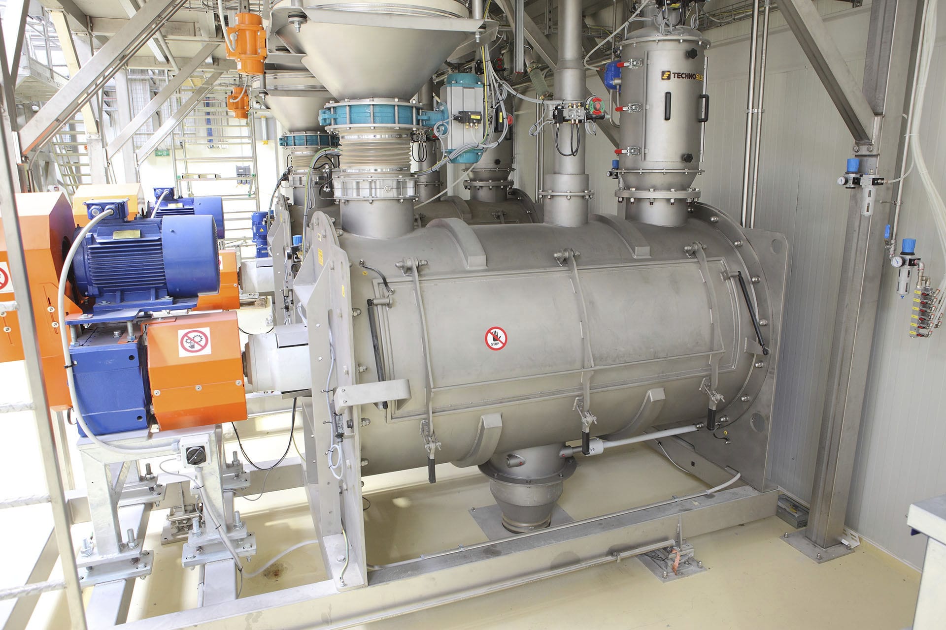







The automatic feeding machine adopts the analog signal output by the PLC as the input signal of the control terminal of the frequency converter. It controls the speed of the motor by receiving the signal from the PLC and feeds back its own working status signal to the PLC. When a fault occurs, it can send an alarm signal to the PLC and the upper computer. Since variable frequency speed regulation is achieved by changing the synchronous speed by altering the power supply frequency of the motor stator, a limited slip power can be maintained from high speed to low speed during the speed regulation process.


 020-34563445
The automatic Feeding machine is required to be capable of centralized control of the start and stop of the motor, viewing the production flow chart, responding to accident alarms, automatically adjusting the operating speed of the feeding motor, adjusting the operating speed of the classification motor at any time, displaying real-time data such as weight and current, and regulating the rotational speed of the feeding motor and the classification motor. The motor's start-up, operation, speed adjustment and braking feature high functional versatility of a V/F universal inverter. The analog signal output by the PLC is used as the control input signal for the inverter. By receiving the signal from the PLC, the motor speed is controlled, and the working status signal of the motor is fed back to the PLC. When a fault occurs, an alarm signal can be sent to the PLC and the upper computer. Since frequency conversion speed regulation is achieved by changing the supply frequency of the stator of the motor to change the synchronous speed, during the speed adjustment process, a limited slip power can be maintained from high speed to low speed.
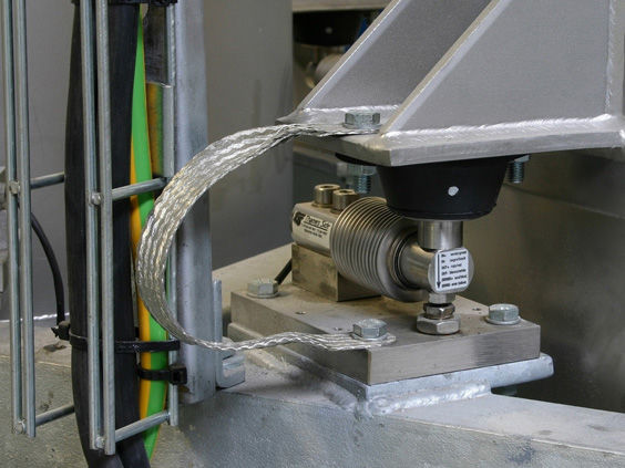
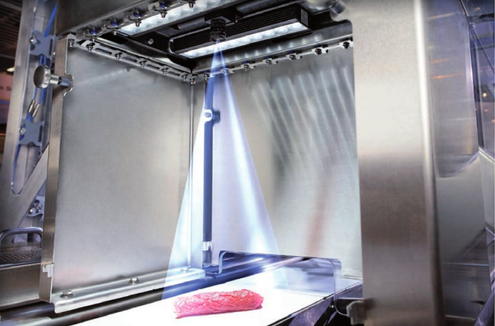
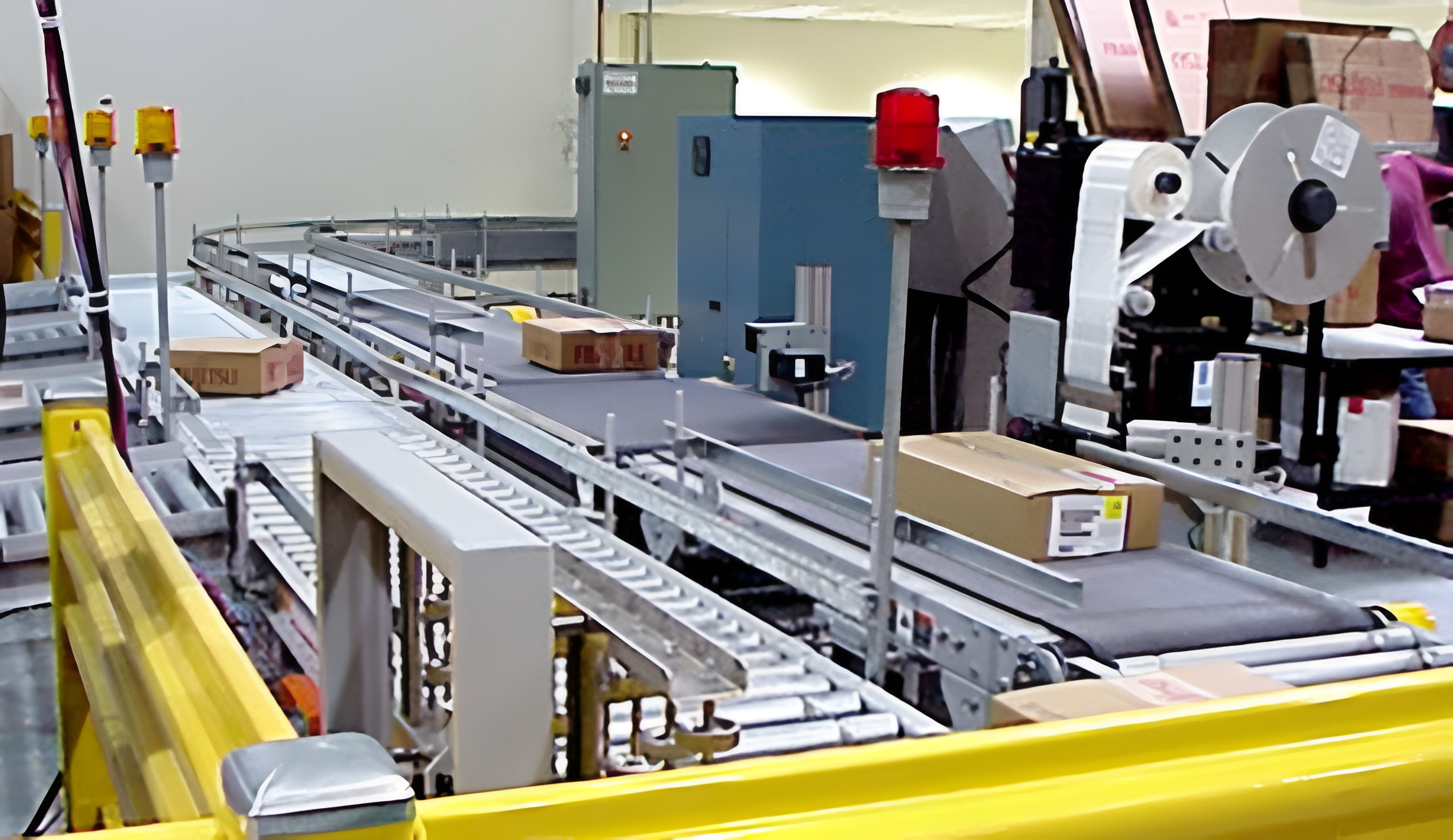
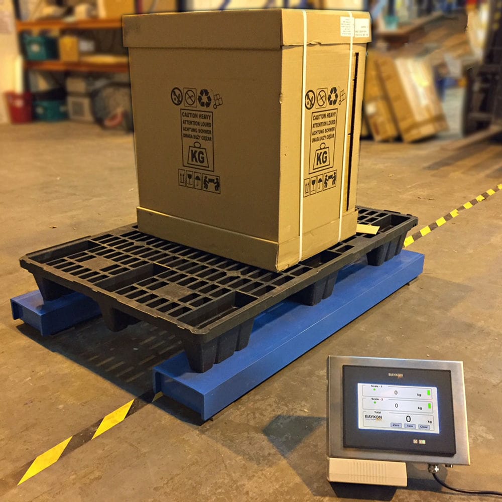
The weighing module serves as the Weighing system for the Feeder to detect the weight. On the weighing touchscreen, the amount of the material to be loaded by the feeder is set. If the set loading material is less than the minimum limit material loading capacity or greater than the maximum limit material loading capacity, the system will issue an alarm. When the input loading material amount is within the set loading material range, a comparison operation is performed with the internal set value of the system. The PLC outputs control to start the third-level conveyor belt in sequence from the lower level to the upper level to discharge the material. If the loading material amount is less than or equal to 10% of the set material loading capacity, the conveyor operates at a low speed; if the loading material amount is more than 10% of the set material loading capacity, the conveyor automatically switches to high-speed operation, and the material discharge also increases, thereby increasing the conveying speed and shortening the material loading time. When the loaded material reaches 90% of the set loading capacity, the conveyor automatically switches to low-speed operation, the material discharge is reduced, and when the material loading reaches 100% of the set value, the conveyor automatically stops, and the material loading is completed.
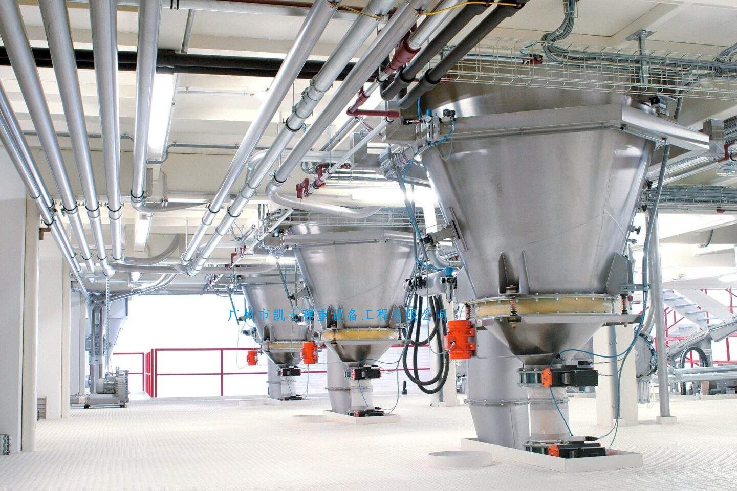
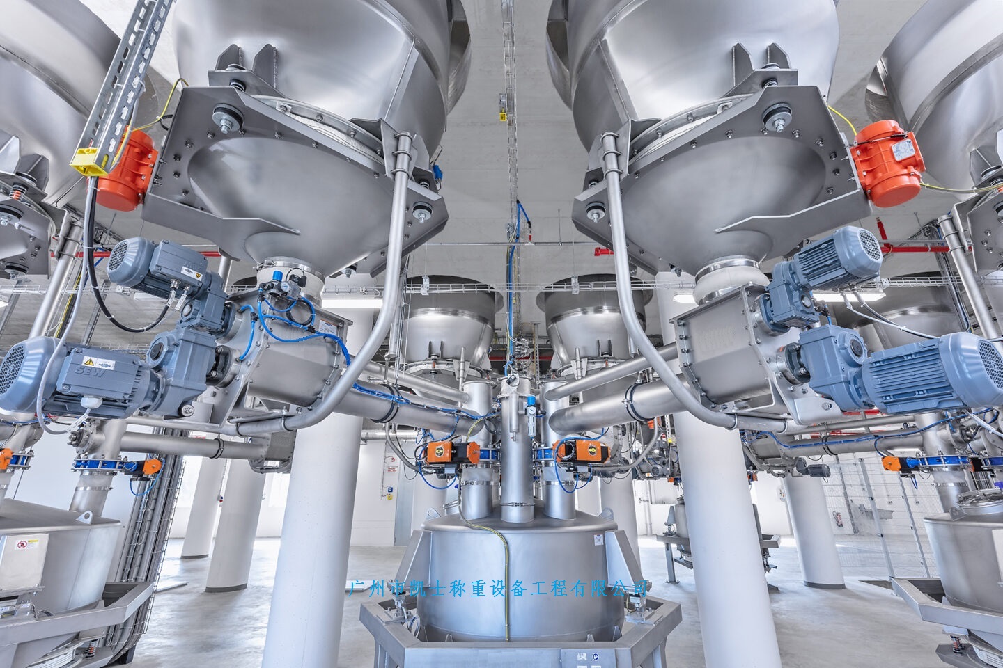
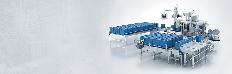
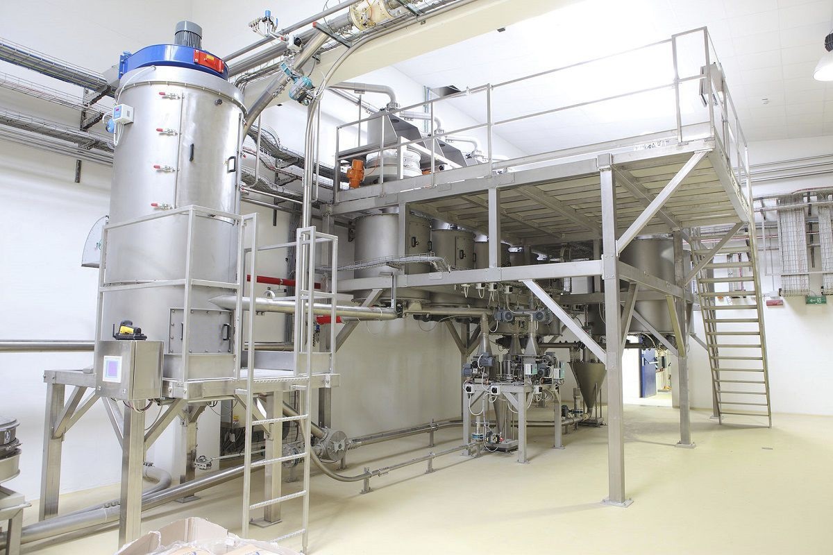
The batching machine is mainly composed of a screw feeder, a buffer hopper, a hopper scale, a speed control motor, an Electronic scale, etc. It controls the feeder, the buffer hopper, the hopper scale and the hopper door mechanism. The feeder is composed of two different-sized spiral propellers. During the high-speed loading stage, the double-wound wheels operate at high speed simultaneously to increase the loading speed. During the low-speed fine adjustment stage, the clutch disengages the large pulley and the large pulley alone is used for loading. The entire loading process is equipped with the stepless speed regulation characteristic of the slip differential motor, thus enabling precise loading. At the front end of the weighing screw machine's impeller, a special structure with multiple blades and a short section at the tip is adopted, which greatly improves the uniformity and stability of the material flow, especially at low-speed material flow, thereby effectively enhancing the weighing accuracy.
The buffer hopper consists of a storage bin and a double-leaf gate. It is connected to the outlet of the screw feeder. When the material approaches the rated value, the buffer gate is closed to intercept the materials remaining in the air and reduce the drop height, thereby minimizing the impact of the materials on the measurement accuracy. The hopper scale consists of a storage bin, an electronic scale mechanism, and a double-leaf gate. It adopts a suspended structure. The electronic scale suspends the hopper scale in a symmetrical structure through a double-linkage structure. The weight of the object is converted into an superposition mV signal by the electronic scale and sent to the PLC for processing. This structure eliminates the problem of force point offset caused by the uneven distribution of materials within the hopper scale, thus avoiding signal distortion. The door of the hopper is all equipped with a pull-rod interlock mechanism, which is controlled by the electronic scale and has a fast response speed and good consistency. In the electronic scale mechanism, a damping device is added to reduce the influence of mechanical vibration on the electronic scale signal.
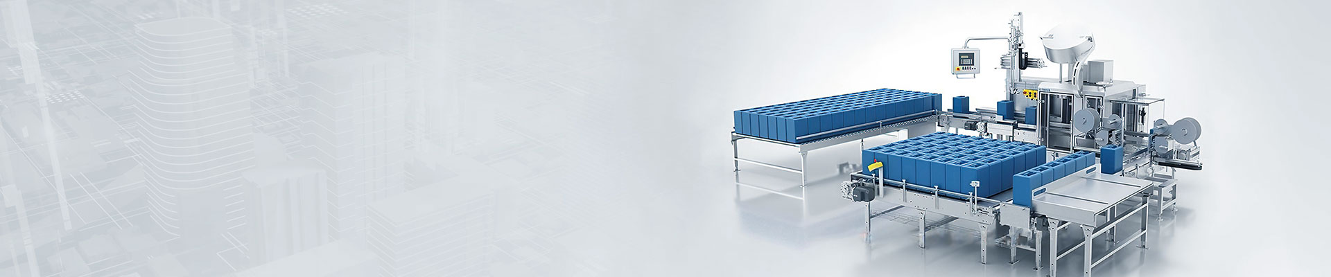
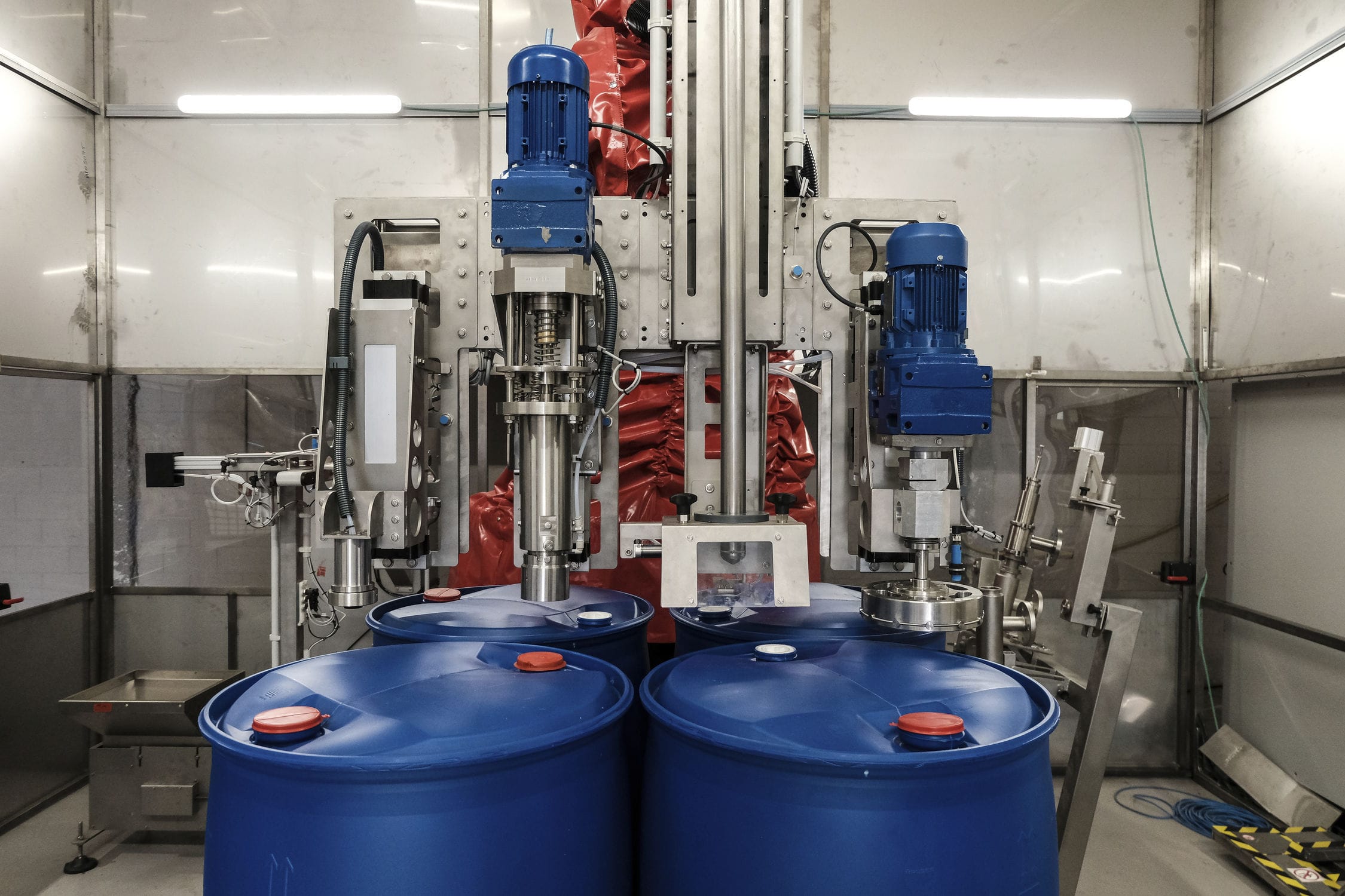
The powder output by the batching machine is directly transported through the conveyor and sent to the packaging workshop via a buffer silo. In the packaging workshop, multiple dynamic quantitative electronic scales and corresponding packaging machinery are installed according to the production scale. The incoming material from the conveyor is divided into multiple discharge ports to separately send the powder into the buffer silo of each dynamic quantitative electronic scale. The PLC controls the screw feeder of the quantitative electronic scale to change speed and send the powder into the hopper scale, and simultaneously detects the weight (flow rate) of the powder in the hopper scale through the electronic sensing element in real time. The speed of the feeding machine is controlled according to the control signal, and when the quantitative value is reached, the feeding machine stops and the buffer material door is closed to capture the powder that is suspended in the air, achieving quantitative measurement control. After the quantitative measurement is completed, the PLC determines the status of the discharge switch. If discharge is required, the hopper scale door is opened to pour the powder into the packaging machinery, and the packaging machinery completes bagging and sealing.