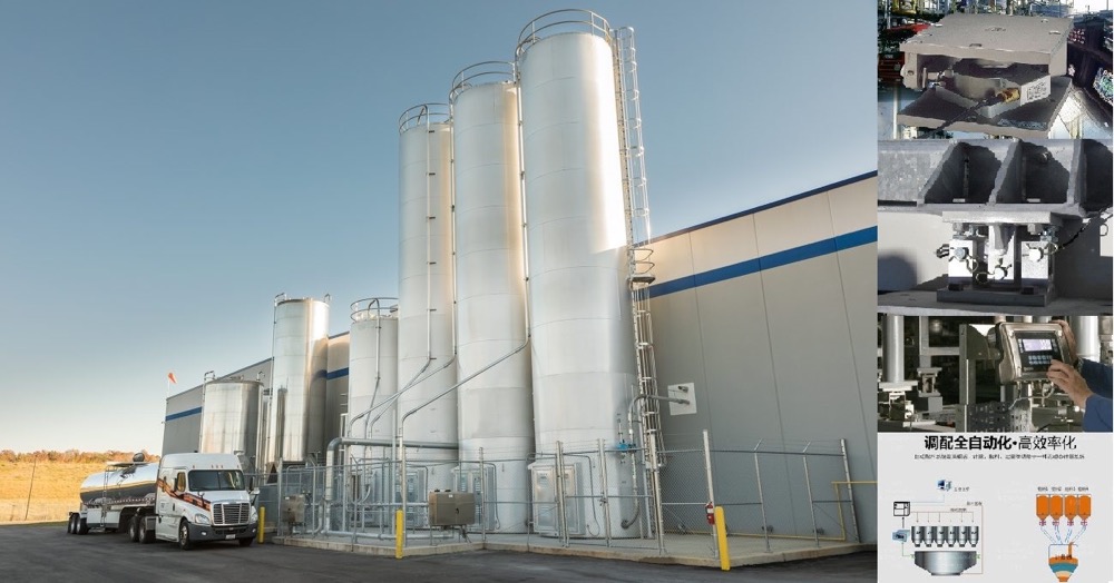




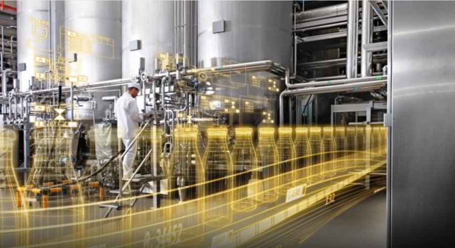


The automatic weighing filling machine provides dual power supplies or industrial Ethernet communication modules for each subsystem and combines them. The safe, reliable and advanced practical system design selects mature and advanced distributed computer control systems, which are transmitted to the central control room through a high-speed network for centralized monitoring and management. The central control room host also transmits control commands through a high-speed network to the PLC measurement and control terminal to implement decentralized management of each unit.

 020-34563445
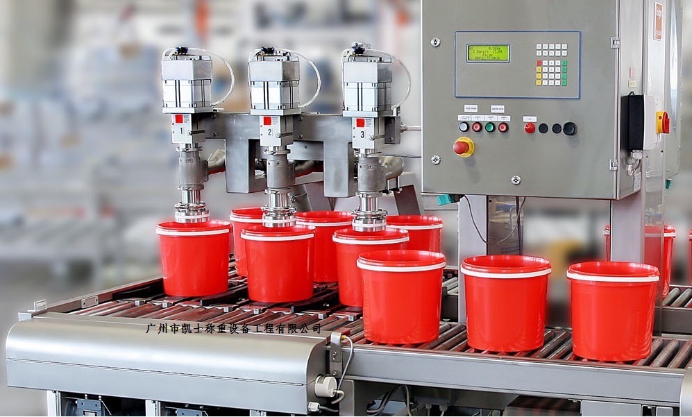
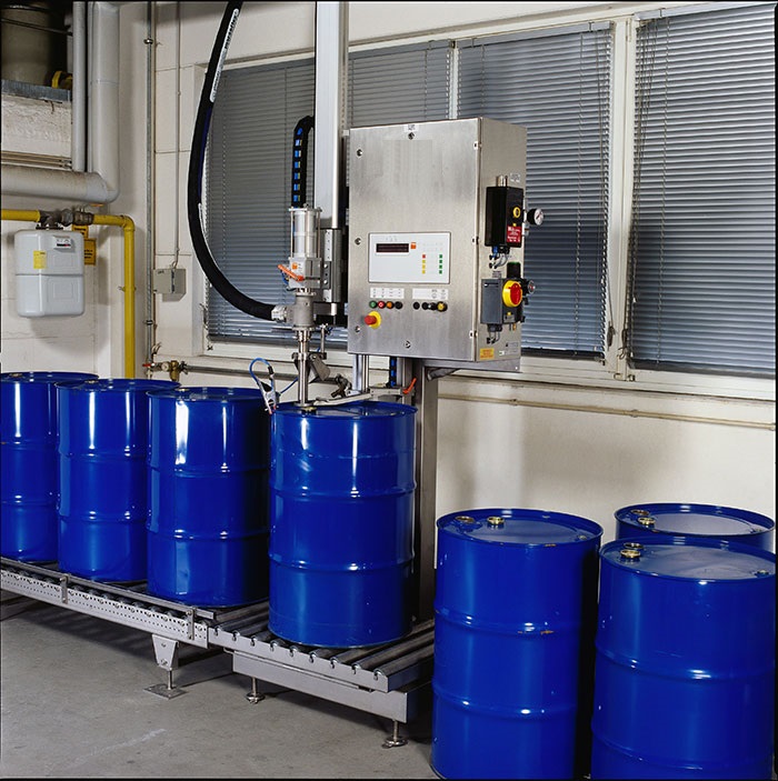
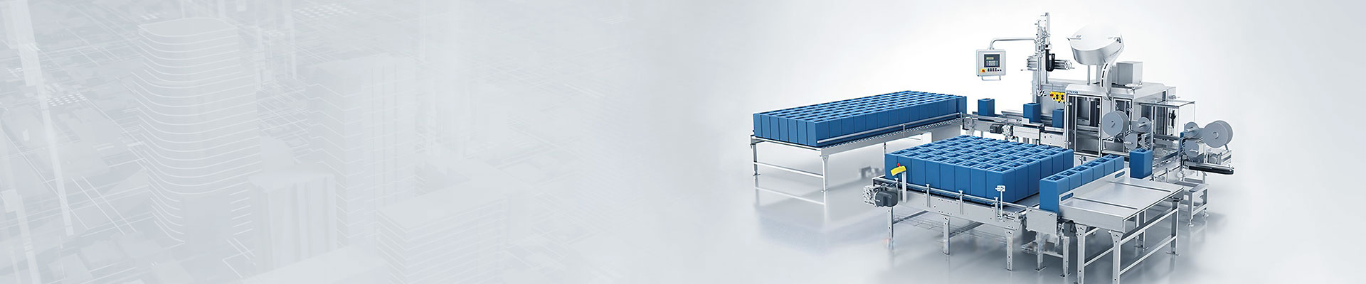
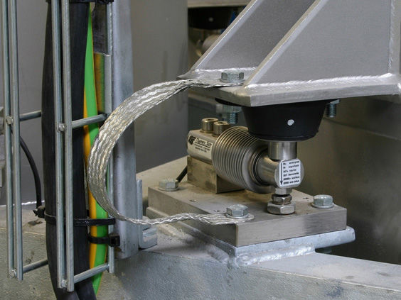
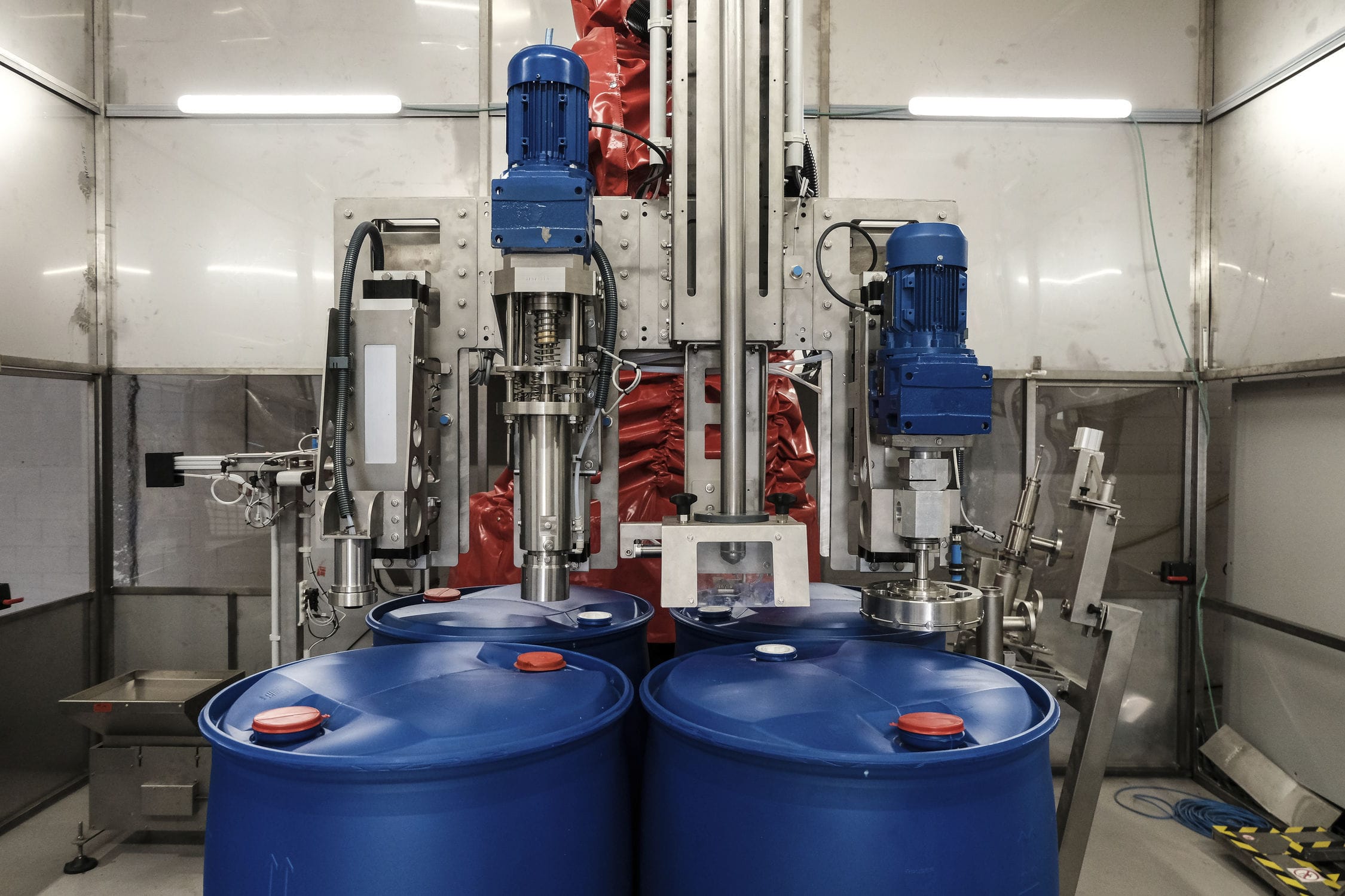
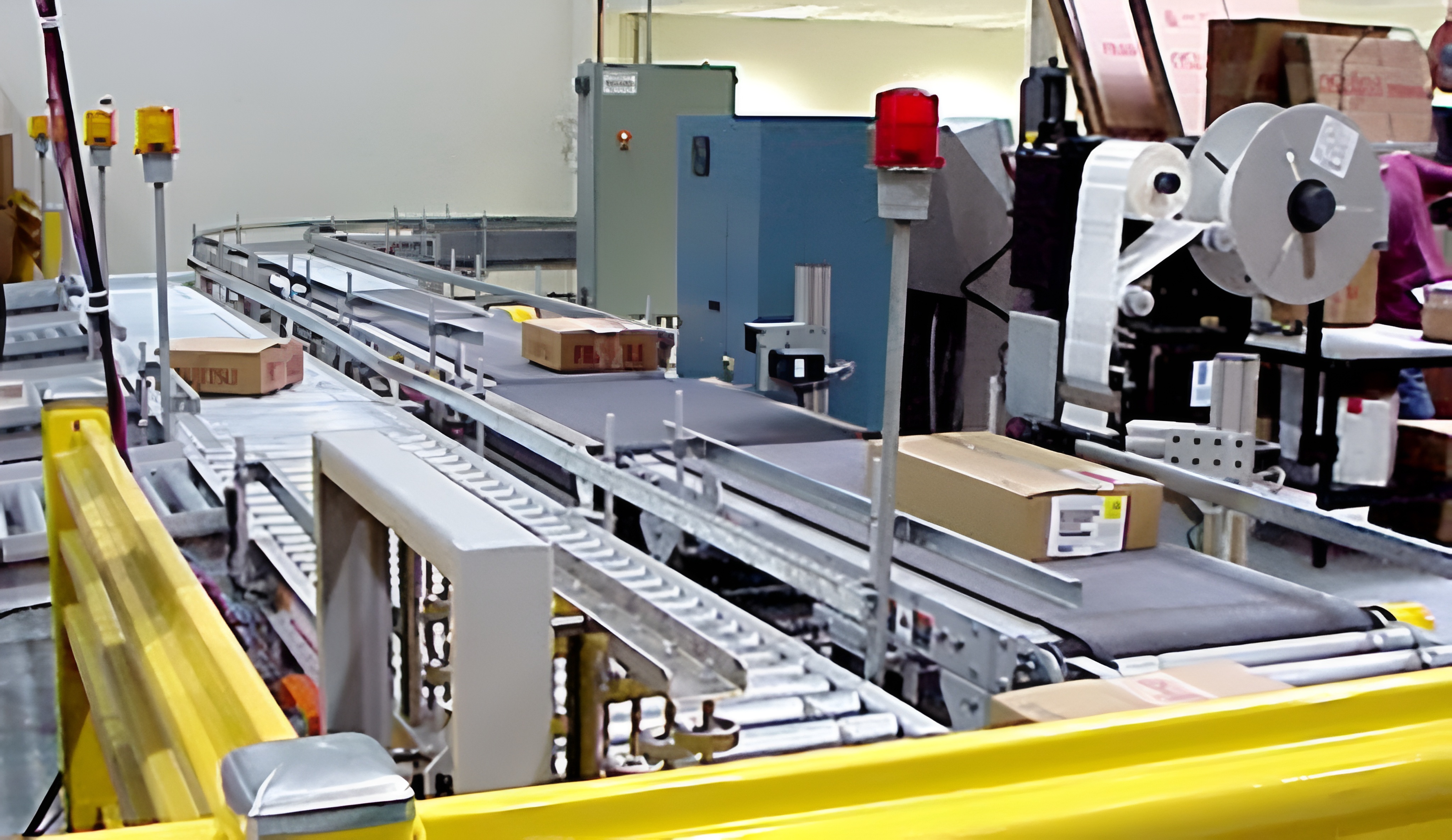
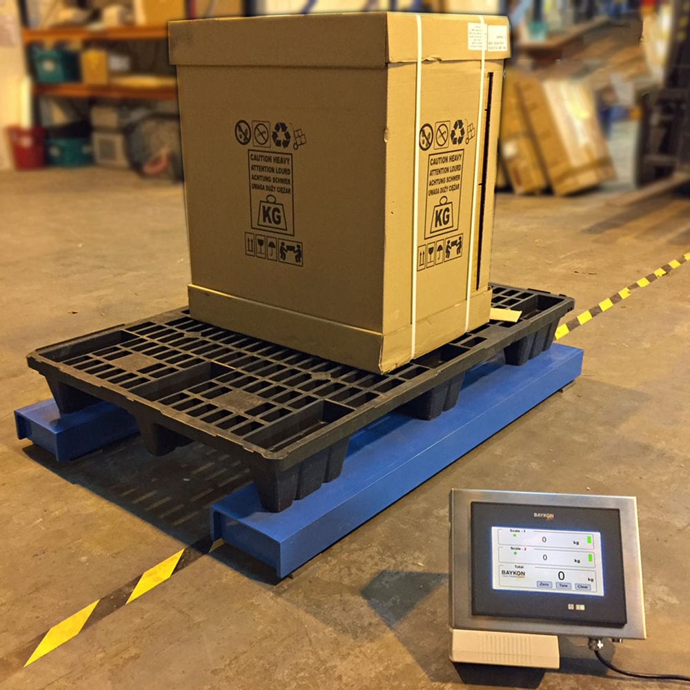
The automatic weighing and Filling machine uses weighing instruments to collect data through Weighing modules and perform calculations to control the execution components, achieving automatic weighing and unloading of materials for filling. The measuring filling machine is a weighing instrument that controls only one measuring bucket, consisting of a weighing instrument, material preparation bucket, measuring bucket, discharge bucket, weighing sensor, filling machine, bracket, etc. The material is fed into the preparation bucket by the feeding motor, and then enters the measuring hopper from the preparation bucket. The weight of the material in the measuring hopper is collected by the weighing module through A/D conversion by the weighing instrument. The weighing instrument continuously collects data and calculates the current feeding speed of the measuring hopper based on the collected time difference. Then compare the pre-set value with the weight of the material in the current measuring bucket and calculate the time needed to continue feeding. The Liquid filling machine continuously collects data and makes judgments to calculate the new feeding speed and required feeding time. In addition, the feeding port size of the material preparation bucket and the measuring hopper is controlled by a weighing instrument, which can ensure the accuracy of the measurement. The weighing instrument controls the size of the feeding port of the ingredient bucket. At the beginning, the feeding port is the largest (large feeding). When the weight of the material in the measuring bucket approaches 70%~80% of the set value (specifically set by the software part of the weighing instrument), the feeding port shrinks partially (medium feeding). When it approaches 80%~95% (specifically set by the software part of the weighing instrument), the feeding port shrinks to the smallest feeding port (small feeding). Finally, when the weight of the material in the measuring bucket plus the weight of the material falling from the air reaches the set value, the feeding port of the material bucket is closed and the weighing is completed. The measuring bucket can be unloaded into the filling bag for sealing. The automatic filling machine adopts a cabinet, a material tank, a filling mechanism, a container feeding mechanism, a container sending mechanism, a weighing and filling scale, and a container pushing mechanism. The material tank is fixed at the top of the cabinet, the filling mechanism is set inside the cabinet and connected to the material tank, the container feeding mechanism penetrates from one side of the cabinet, and the container sending mechanism exits from the other side of the cabinet. The weighing and filling stainless steel scale is set inside the cabinet and is located between the container feeding mechanism and the container sending mechanism, and is also located directly below the filling mechanism. The container pushing mechanism is set inside the cabinet, and the container pushing mechanism pushes the container to move between the container feeding mechanism, explosion-proof scale, and container sending mechanism. The quantitative feeding mechanism includes a fixed feeding rack, a movable feeding rack, a feeding rack driving device, a feeding pipe, a feeding cylinder, and a feeding nozzle. The fixed feeding rack is fixed inside the cabinet, and the movable feeding rack is connected to the fixed feeding rack by sliding up and down; The driving device of the feeding rack drives the movable feeding rack to move up and down; Multiple filling pipes are evenly arranged side by side on the active filling rack. A filling cylinder is set at the top of the filling pipe, and a filling nozzle is set at the bottom of the filling pipe. The side of the filling pipe is connected to the material tank. The feeding rack driving device of the feeding mechanism adopts a feeding rack driving motor, a feeding rack driving shaft, a driving sprocket, a driven sprocket, and a chain. The feeding rack driving motor is fixed on the fixed feeding rack, and one end of the feeding rack driving shaft is fixedly connected to the driven shaft of the feeding rack driving motor, while the other end is rotatably set on the fixed feeding rack. The driving sprocket and the driven sprocket are respectively installed on the feeding rack driving shaft and the fixed feeding rack, and the chain surrounds the driving sprocket and the driven sprocket. The movable feeding rack is fixedly connected to the chain. The discharge end of the filling nozzle of the liquid filling mechanism is conical and evenly distributed with multiple discharge small holes. The container is a barrel shaped container. The container feeding mechanism includes a star wheel device, as well as a barrel conveying belt device, a chain acceleration device, and a barrel feeding conveyor belt device arranged in sequence. The star wheel device is set on one side of the barrel conveying belt device adjacent to the chain acceleration device. The star wheel device pulls the tightly arranged barrel shaped containers sent by the barrel conveying belt device onto the chain acceleration device one by one. The chain acceleration device accelerates the barrel shaped containers to be fed into the barrel conveying belt device, so that the distance between the barrel shaped containers increases after entering the barrel conveying belt device. The star wheel device of the container feeding mechanism includes a star wheel and a star wheel drive motor that drives the rotation of the star wheel. The star wheel includes a wheel axle and multiple blades evenly distributed on the outer circumference of the wheel axle. One side of the blades is provided with an arc-shaped groove that matches the outer circumference of the barrel shaped container. The barrel feeding conveyor belt is equipped with multiple stop bars at equal intervals.
The chain acceleration device of the container feeding mechanism includes a chain bracket, a chain drive motor, a first shaft, a second shaft, a third shaft, a fourth shaft, a bottom chain component, an intermediate chain component, and a top chain component. The chain drive motor is fixed on the chain bracket, and the first shaft, the second shaft, the third shaft, and the fourth shaft are all rotated and set on the chain bracket. One end of the first shaft is fixedly connected to the chain drive motor. The active sprocket of the bottom chain component is fixed on the first shaft, the driven sprocket of the bottom chain component and the active sprocket of the intermediate chain component are fixed on the second shaft, the driven sprocket of the middle chain component and the active sprocket of the top chain component are fixed on the third shaft, and the driven sprocket of the top chain component is fixed on the fourth shaft. On the axis, The top chain component is horizontally set, and both the bottom chain component and the middle chain component have a driving sprocket diameter larger than the driven sprocket diameter. The driving sprocket and the driven sprocket diameter of the top chain component are the same, and at least one set of top chain components is provided. The chain bracket is equipped with a support bar corresponding to the top chain component, and the chain of the top chain component wraps around the upper end face of the corresponding support bar. The container is a bucket shaped container, and the container pushing mechanism is set below the container feeding mechanism, the material bucket weighing scale, and the container sending mechanism. The container pushing mechanism includes a bucket pushing frame, a bucket pushing guide rail, a bucket pushing slide plate, a slide driving device, a lifting driving device, a bucket pushing top plate, and a bucket pushing rod assembly. Multiple bucket pushing guide rails are parallel to the bucket pushing frame, and the bucket pushing slide plate is set on the multiple bucket pushing guide rails. The slide driving device is installed on the bucket pushing frame and drives the bucket pushing slide plate to slide on the bucket pushing guide rail. The lifting driving device is fixed on the bucket pushing slide plate, and the bucket pushing top plate is installed on the lifting driving device. The lifting driving device drives the bucket pushing top plate to move up and down. There are multiple sets of bucket pushing top plates on the bucket pushing top plate. The bucket rod assembly corresponds to the bucket shaped container, The bucket pushing rod assembly includes two parallel connecting plates and four bucket pushing rods respectively set at the top of both ends of the two connecting plates. The bucket pushing rods are vertically set, and the container feeding mechanism, double-layer weighing scale, and container sending mechanism are all equipped with multiple long through grooves. The upper end of the bucket pushing rod passes through the long through grooves on the container feeding mechanism, waterproof weighing scale, and container sending mechanism. One side of the upper end face of the bucket pushing frame is equipped with multiple position sensors for sensing the position of the bucket pushing slide. The skateboard drive device of the container pushing mechanism includes a skateboard drive motor, a skateboard drive chain, a transmission shaft, and a synchronous belt component. The skateboard drive motor is fixed on the bucket frame and drives the transmission shaft to rotate through the skateboard drive chain; The active pulley of the synchronous belt component is fixed on the transmission shaft; The sliding plate of the push bucket is fixedly connected to the synchronous belt assembly, and the lifting drive device includes multiple lifting cylinders. The cylinder body of the lifting cylinder is fixed to the sliding plate of the push bucket, and the piston rod of the lifting cylinder is fixed to the bottom of the top plate of the push bucket. The container is a bucket shaped container, and the container pushing mechanism is set above the container feeding mechanism. The container pushing mechanism includes a bucket pushing bracket, a bucket pushing cylinder, and a bucket pushing crossbar. The cylinder body of the bucket pushing cylinder is set on the bucket pushing bracket, and the bucket pushing cylinder drives the bucket pushing crossbar to move between the upper part of the container feeding mechanism and the weighing and filling scale.