


The dual-speed explosion-proof filling machine adopts a design of a cylindrical sliding valve in the filling valve. There is a crescent-shaped groove on the sliding valve, and the size of the groove can simultaneously cover the channel below the filling gun and the upper channel of the piston body, allowing the filling gun and the piston body to be connected. When the sliding valve rises, the channel of the filling gun is covered, and the channel on the piston body and the channel on the filling valve are connected. During the operation of the filling machine, the piston rod descends under the action of the cam, and the channels are connected. The liquid material enters the piston body through the channel at the bottom of the filling gun, the crescent-shaped groove of the sliding valve, and the channel.

 020-34563445
The dual-speed explosion-proof Filling machine is composed of an Electronic scale, a PLC control system, a filling mechanism, a conveyor, a rotor pump, etc. When the filling container is placed on the electronic scale platform, the electronic scale will detect the weight of the material bucket on the platform and transmit the signal to the PLC system. The electronic scale will convert the signal into a digital signal and transmit it to the PLC system. The PLC system will calculate the amount of liquid to be filled based on the preset filling volume and filling speed, and transmit the signal to the weighing instrument. The weighing instrument will control the filling speed and volume of the filling machine according to the instructions of the PLC system to achieve the preset filling target. The controlled piston filling chamber realizes quantitative control, and the piston displacement is achieved through a servo encoder or a high-precision displacement piston rod for closed-loop control.
The automatic filling machine adopts a filling valve with a cylindrical sliding valve design. There is a crescent-shaped groove on the sliding valve, and the size of the groove can simultaneously cover the channel below the nozzle and the upper channel of the piston body, making the storage nozzle and the piston body connected. When the sliding valve rises, the channel of the storage nozzle is covered, and the channel of the piston body and the channel of the filling valve are connected. During the operation of the filling machine, the piston rod descends under the action of the cam, and the channels are connected. The liquid material enters the piston body through the channel at the bottom of the storage nozzle, the crescent-shaped groove of the sliding valve, and the channel. When the empty bucket reaches the bucket support, the bucket support is lifted by the cam, the bucket mouth presses the filling head and the sliding valve rises, the sliding valve covers the channel and connects the filling valve channel and the piston channel at the same time. At this point, the piston rod rises under the action of the cam, and the liquid material in the piston filling gun is pressed into the bucket above the electronic scale. The air in the bucket is discharged through the pores on the filling head. When the piston rises to the highest point, one filling is completed. Immediately after, the filled bucket is moved downward under the action of the cam, while the sliding valve is reset by the spring, and the crescent-shaped groove of the sliding valve reconnects the channels. The material in the storage nozzle flows into the piston body through the storage nozzle, and the piston rod also moves downward under the action of the cam, for the next filling. During some liquid filling processes, foaming is prone to occur, and if the filling speed is too fast, it is easy to splash out. The controlled piston filling chamber has a three-stage adjustment PID function, which compares the feedback signal from the encoder with the given signal to obtain the error signal, and performs PID control according to the size and rate of error change. The actual control variable of liquid filling is the filling volume, and the filling volume can be changed by adjusting the oil pressure of the oil cylinder through the control valve. Increasing the proportional coefficient speeds up the filling speed, and the PLC system controls the three-stage adjustment of the filling gun filling volume by the lifting cylinder, and slows down the control of the differential time to help eliminate the filling bubbles. By modifying the touch screen data to reasonably select control parameters to achieve the control purpose.
The quantitative filling machine is equipped with a weighing module operation platform, an automatic empty bottle detection, and an above filling valve. The inlet of the filling valve is connected to the inner cavity of the liquid storage tank through a connecting pipe. The liquid storage tank is located on the upper surface of the operation platform, and the outlet of the filling valve is equipped with a pull rod nozzle. The electric telescopic rod is fixedly connected to the other side of the upper surface of the structure of the filling valve, and the upper surface of the operation platform is equipped with a Filling system corresponding to the filling structure. The upper surface of the operation platform is equipped with a PLC control system. The filling machine is connected to two fixed frames through bearings and two conveyor wheels, and the two conveyor wheels are equipped with conveyor belts. One of the conveyor wheels is fixedly connected to the output shaft of the servo motor on the outside of the fixed frame, and the input end of the servo motor is electrically connected to the output end of the PLC controller. The filling head is set on the front side of the bottom of the fixed frame connected to the bottom of the soft pipe and the connection plate of the soft pipe base. The filling head is equipped with an electric fusion chamber, and the input end of the electric fusion chamber is electrically connected to the output end of the PLC controller. The base is set on the upper surface of the operation platform. The upper surface of the base is equipped with a photoelectric sensor, which is located directly below the belt conveying structure and corresponds to the filling head. The photoelectric sensor is bidirectionally electrically connected to the PLC controller. The empty bottle detection system is equipped with a laser displacement transducer, which is also bidirectionally electrically connected to the PLC controller. The weighing and filling machine can perform automatic liquid filling quickly and efficiently. The PLC controller detects the structure to achieve automatic control and adjustment of the filling volume. Through the belt conveying structure and the PLC controller, liquid filling can be carried out quickly and efficiently.
The Liquid filling machine can adjust the speed and size of the filling amount. The filling machine usually uses a component supply screw to supply barrels to the filling machine's tray platform in the required state, spacing, and speed. The barrels are lifted by the tray mechanism and brought into close contact with the filling head for filling. According to the change in the system output volume, one working cycle of the system is decomposed into several consecutive stages. When the filling head reaches the bottom, the filling large valve chamber electromagnetic valve opens, and the oil cylinder pressure is high, performing rapid filling to control the upward and downward filling actions of the oil cylinder. The filling pressure is relatively high, and the oil cylinder runs at a relatively fast speed, resulting in a corresponding high filling speed. When the small valve chamber opens, the oil cylinder pressure decreases, the oil cylinder runs at a slower speed, and the filling is performed at a slow speed. The movement of the oil cylinder drives the PLC shaft encoder to rotate, and the pulse output of the shaft encoder is sent to a high-speed dual-channel to determine whether the liquid level is filled to the preset value. After the first value is reached, slow filling is performed. After the second value is reached, the system considers that the liquid has been filled to the preset value. After a certain delay, the filling head returns to its original position, preparing for the next filling.
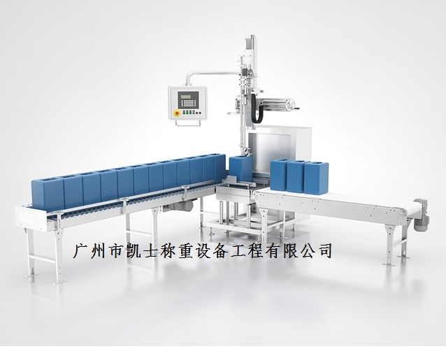
The automatic filling machine consists of a main conveyor belt, a defective product conveyor belt, a filling device, a defective product pushing device, a positioning sensor, and a defective product detection sensor. After the barrel conveying belt enters the electronic scale, the motor's starting device moves up and down and performs filling. The detection and pushing of defective products are controlled by the PLC. The barrels are sent into the barrel tray lifting mechanism at equal intervals through the transmission wheels. When the tray detects the pressure of the electronic scale, the tray piston gives the tray lifting mechanism a pressure, and the tray starts to rise. During the rising time of the tray, the maximum rising time is 6 seconds. If the pressure in the filling port center detection is detected, the tray stops rising, and then the valve opens, starting to fill the barrel. The maximum filling time is 6 seconds. When the valve detects the air pressure, it stops filling, and the liquid valve opens to start filling. Through activating the electromagnetic valve for air pressure conduction, the air pressure valve is controlled to fill the barrel. When the target volume reaches the standard, the air pressure valve stops filling, and the filling port lowers the already filled barrel. Ensure that the screw thread of the barrel cover is aligned with the barrel opening. The barrel rotates with a friction chain conveyor belt to tighten the barrel cover, thereby achieving sealing. After the filling is completed, the tray starts to descend. During the descent, the liquid valve is closed, the exhaust pipe works, and the exhaust and residue removal operation is opened. After the descent is completed, the barrel turns a certain angle by the transmission wheels and is sent out. At the same time, the barrel tray continues to enter the packaging position. At this time, the packaging tape at one end will stick to the side wall of the barrel, and then rotate the barrel body to make the packaging paper wrap the barrel body. After wrapping once, the packaging tape will be cut, and the other end of the packaging tape will be fixedly stuck at the bonding point. The packaging part ends here.


