


The negative pressure conveying system is composed of a weighing system control cabinet made up of PLC, touch screen and various electrical components. The auxiliary weighing system is a detection control box made up of various electrical components. The system control cabinet and the detection control box are connected through multiple control signal lines. The weighing system can achieve both automatic and manual control of the system. The detection control box can perform testing tasks such as starting, stopping, and system emergency stop of individual equipment on site. All kinds of control modes need to be realized through PLC to control the motor and drive the motor.
 020-34563445
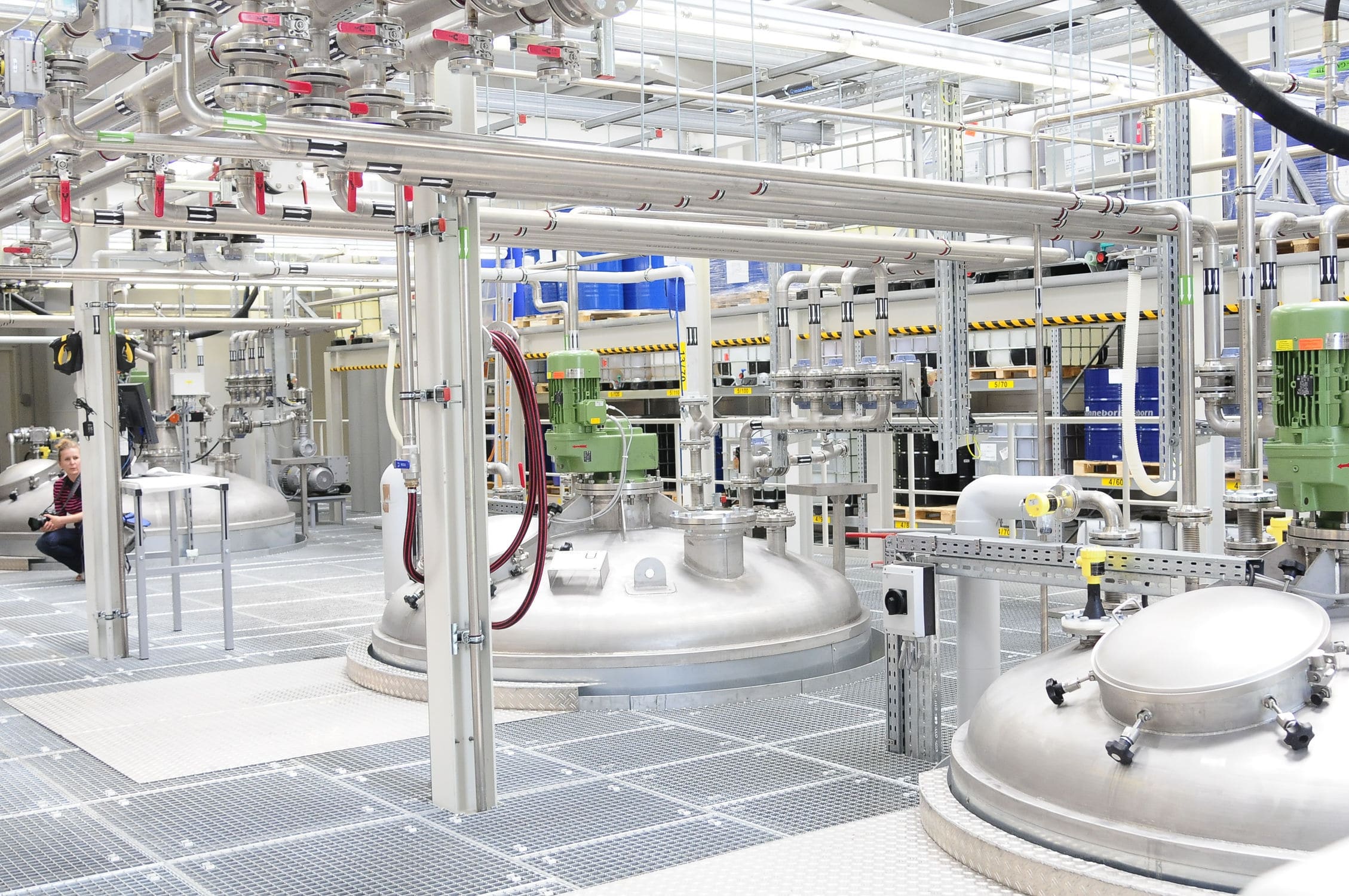
The negative pressure conveying system realizes the function of cleaning and dust removal. It adopts the negative pressure suction pneumatic conveying method based on Roots blower to convey the material silo from the stacking position to the batching room. The impurity cleaning operation of the silo is realized by using a rotary vibrating screen. The dust removal operation of the silo is realized by using a centrifugal unloader and a pulse dust collector. When the working indicator lights of each device on the touch screen are in standby mode, the working indicator lights are yellow. When the equipment is in operation, the indicator light is green. When the equipment is in a faulty state, the indicator light is red. The indicator lights can not only visually reflect the sequential start and stop processes of the system, but also directly indicate the operation status of the equipment during the working process.
The negative pressure conveying system is composed of a Weighing system control cabinet made up of PLC, touch screen and various electrical components. The auxiliary weighing system is a detection control box made up of various electrical components. The system control cabinet and the detection control box are connected through multiple control signal lines. The weighing system can achieve both automatic and manual control of the system. The detection control box can perform testing tasks such as starting, stopping, and system emergency stop of individual equipment on site. All kinds of control modes need to be realized through PLC to control the motor and drive the motor. By using the limit travel switches on the electric gate and the electric suction nozzle, the current opening degree of the electric gate and the electric suction nozzle is expressed as a percentage based on the total time when the motor operates from the fully closed limit position to the fully open limit position and the actual operating time of the motor. The specific process is as follows: First, control the motor to reverse until the fully closed limit travel switch operates. Let the time at this moment be 0 and the opening degree be 0. Then control the motor to rotate forward until the valve is fully open and the limit switch operates. After controlling the reverse rotation time of the motor, stop it. At this time, the opening degree of the electric gate and the electric suction nozzle is approximately 60%. Display the opening degree value through the opening degree bar and percentage numbers.
After the discharge timer ends, if the discharge tank cannot be emptied, it indicates that there is a powder bridge between the discharge tank and the feeding tank. The weighing system will automatically start the bridge removal program. Open the nitrogen valve from the bottom of the discharge tank to the pipeline purifier and the nitrogen valve to the air distributor. At the same time, start the bridge removal timer. During the bridge removal period, close the valves at the bottom of the discharge tank and on the balance pipeline to isolate the discharge tank from the feeding tank. After the bridge removal process is completed, close the nitrogen valve and reopen the pressure balance pipeline between the discharge tank and the feeding tank. Before the bridge removal timer ends, if the discharge tank is empty, the sequence control program will be re-entered; otherwise, the bridge removal program will be entered. The control program allows for two bridge removal processes. If the discharge tank has not been emptied after the two bridge removal program operation cycles, the program will be stopped and an audible alarm will be issued. At this point, the operator has two options: (1) If the low material level signal of the feeding tank disappears, simulate the low material level signal. (2) If the low material level signal of the feeding tank still exists and there is no low material level signal of the discharging tank, restart the bridge removal program.
A vent cone is set at the bottom of the feeding tank. Nitrogen is filled into the vent cone through a nitrogen control valve to ensure the stability of the powder flow rate at the outlet of the feeding tank. Under normal circumstances, the high-pressure nitrogen regulating valve is controlled by flow. When the vent cone pipe is blocked or the pressure difference on both sides of the vent cone increases due to other reasons, in order to ensure that the vent cone does not rupture or get damaged, the weighing system switches to pressure difference control.
The feeding tank is equipped with a pressure control valve and adopts two control methods: pressure and pressure difference. During the purging of the gasification tank, the powder is recycled back to the conveying system through the circulating pipeline, and at this time, pressure control is adopted. After starting the valve for batching, a pressure difference control method is adopted to maintain the pressure difference between the feeding tank and the gasification tank. The pressure of the feeding tank is maintained within the set value range by pressurizing the feeding tank through valve A or discharging nitrogen from the powder filter through valve B.
The discharge tank is pressurized with high-pressure nitrogen. A portion of the nitrogen directly enters the tank through the vent vertebrae at the bottom. To protect the vent plate of the vent vertebrae, a differential pressure control valve is installed on the nitrogen pressurization pipeline. During the pressurization or bridge removal period, the differential pressure control valve controls the nitrogen pressure entering the vent cone and the pressure difference at the top of the discharge tank. This control only receives the start and stop instructions of the sequential control program.
Before connecting the balance pipeline between the discharge tank and the feeding tank, the pressure balance control between the feeding tank and the discharge tank is achieved by adjusting the discharge volume from the discharge tank to the powder filter. This control is only used during the input process of the sequential control program.
When the material level height of the powder storage tank reaches the maximum allowable material level, the grinding and drying subsystems are stopped through interlock control. During the start-up and shutdown of the gasification tank, the powder material returns to the powder storage tank through the circulation pipeline at the inlet of the batching nozzle of the gasification tank.
There are two different pressure grades in the conveying system. The powder storage tank is the low-pressure grade, the feeding tank is the high-pressure grade, and the discharge tank switches the pressure grade according to the filling and discharging volume. To prevent backflow and overpressure, it is necessary to always ensure the isolation between the low-pressure and high-pressure systems, that is, during the filling period of the feeding tank, the low-pressure state should be maintained, and all valves connected to the feeding tank should be locked for operation. During the discharge period, the discharge tank is under high pressure, and all valves leading to the powder storage tank and the powder filter are locked.


