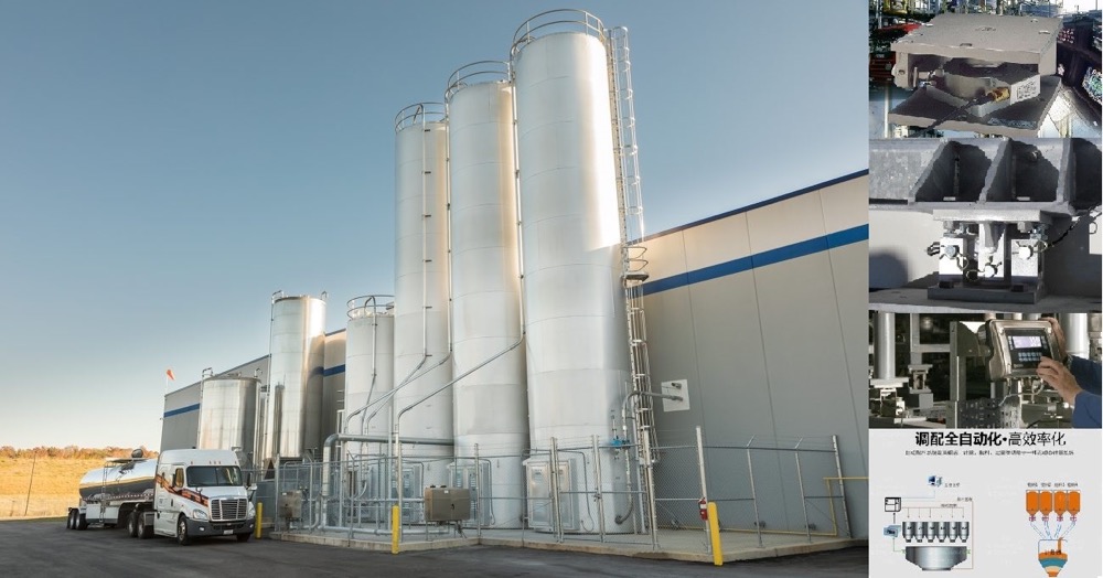


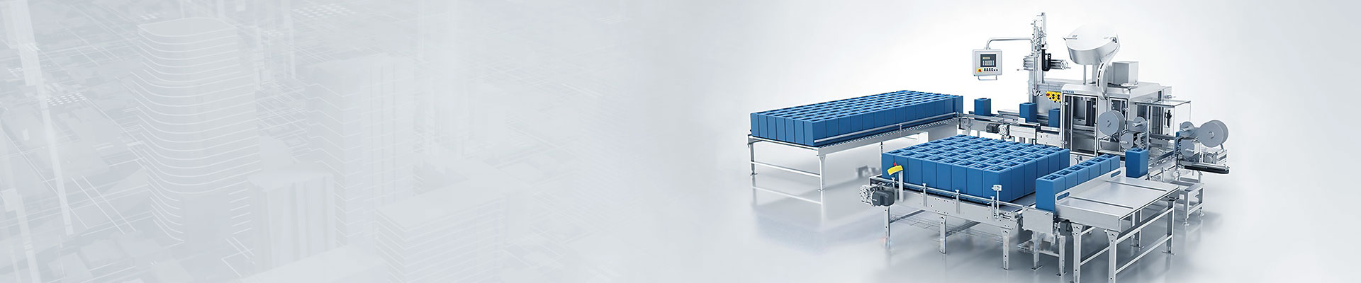



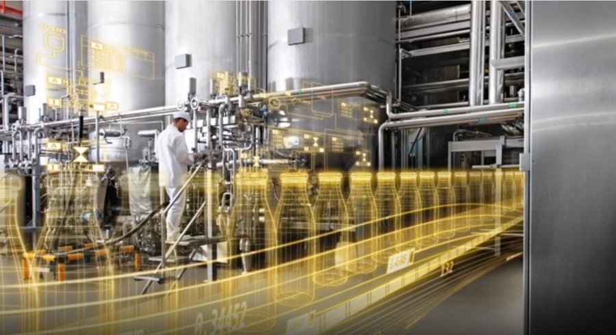
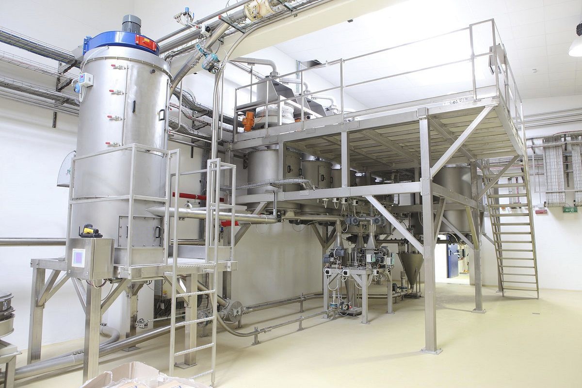
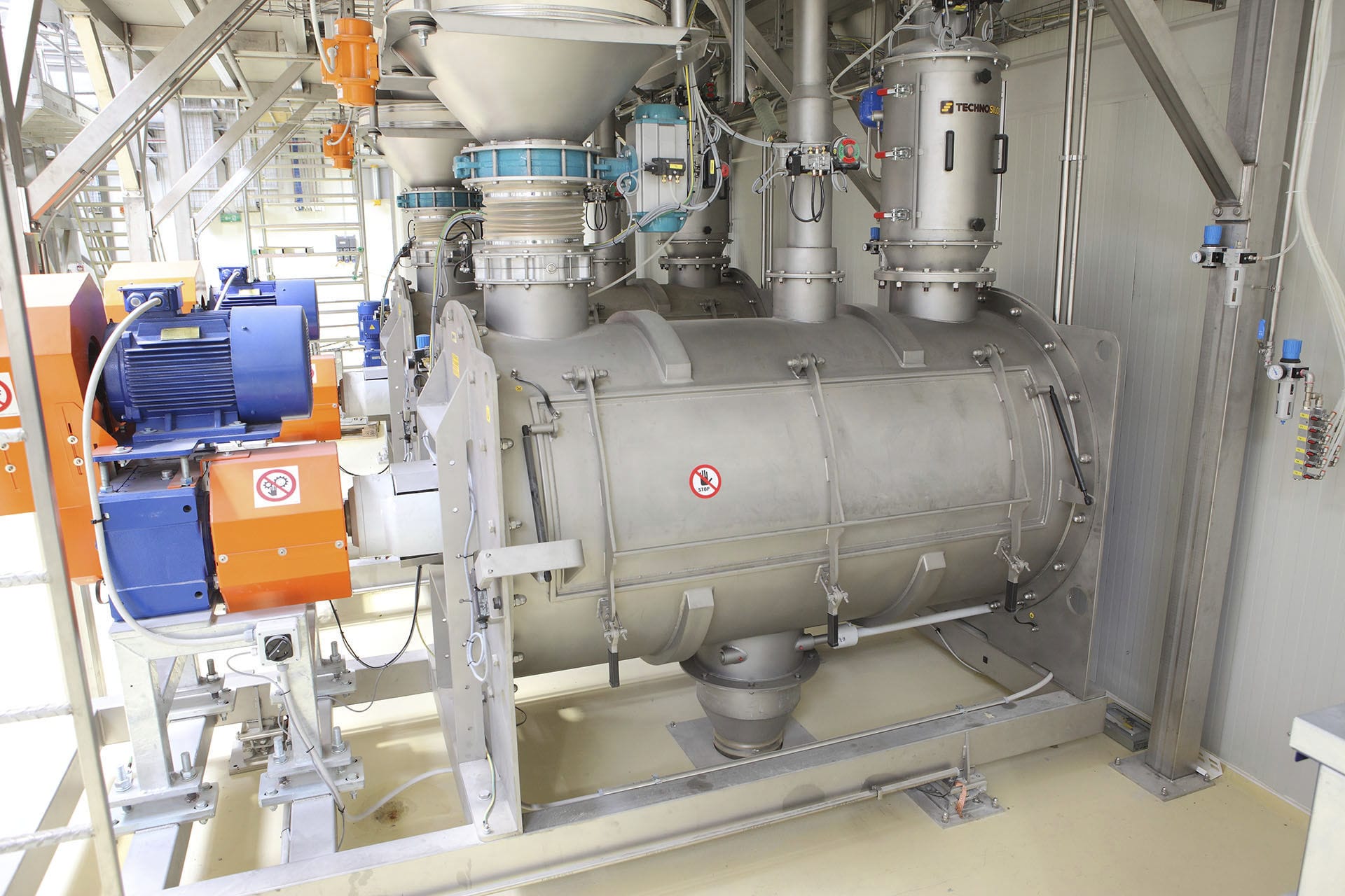
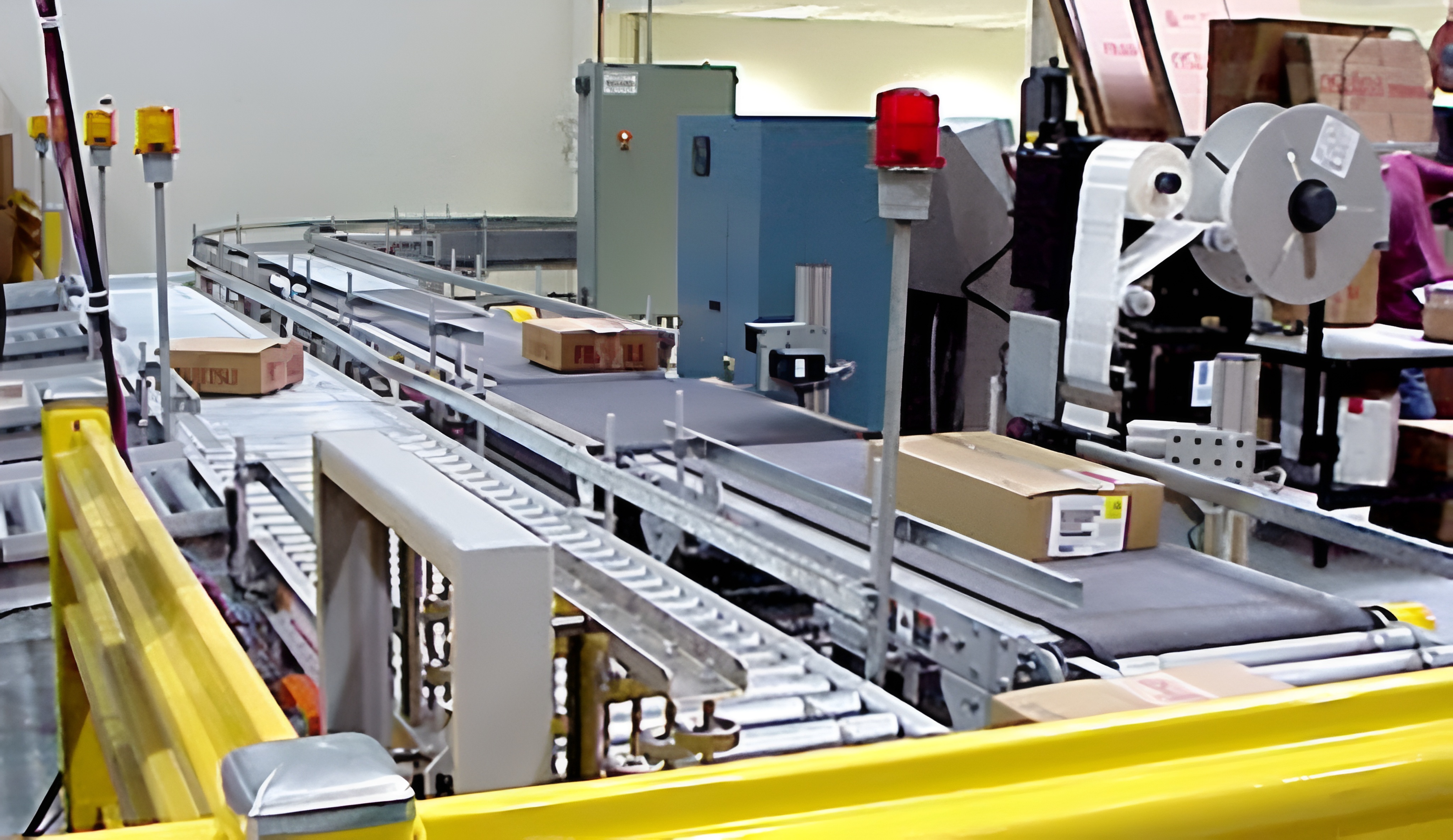


The batching equipment adopts S7-300 and ET200 as the control, data calculation, storage and management of the whole batching to realize centralized monitoring and decentralized control. It mainly consists of feeding system, weighing system, mixing and conveying system and central control system, and through the central control system, each sub-system will be integrated and intelligently controlled to achieve the purpose of energy saving and consumption reduction. The batching production and melting production are closely connected to complete the seamless linkage of resin raw material supply and consumption, eliminate the misjudgment of production conditions, reduce the stagnation, misbehavior and disturbance, and improve energy efficiency. Relying on the monitoring of the current dosage operating parameters introduced into the production process, automatic correction at each process conversion point, so that each process dosage in the entire system production process to give full play to the unit time brought about by the improvement in accuracy, to achieve the best fit.


 020-34563445
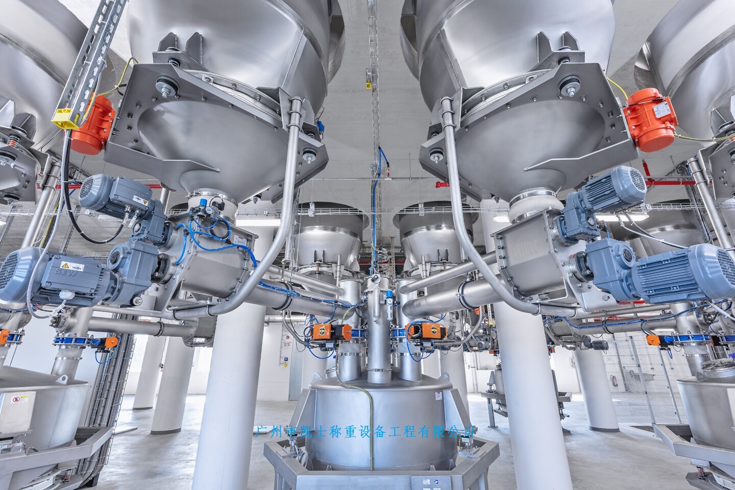
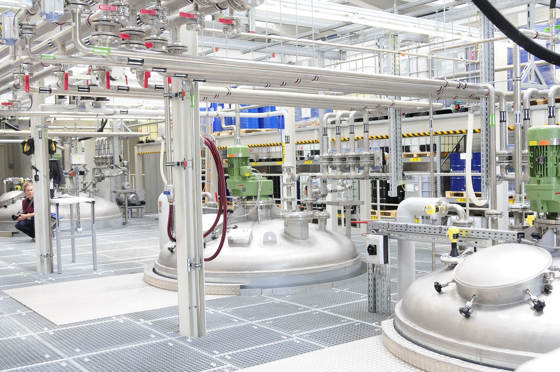
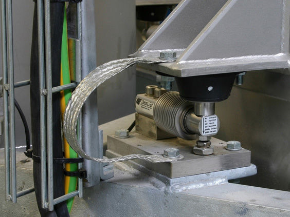
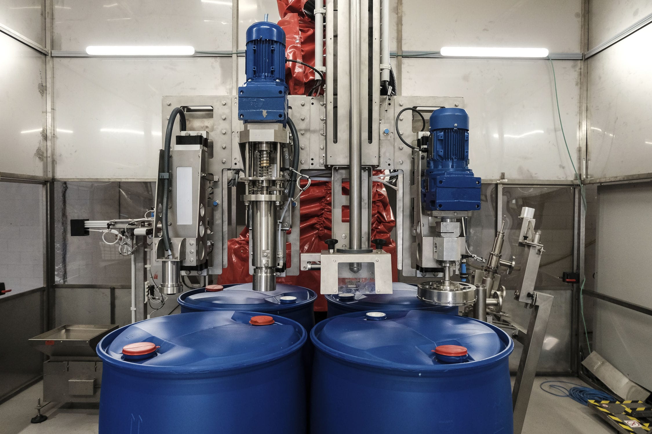
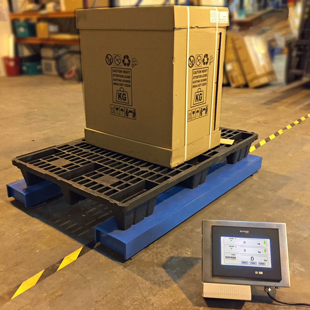
The reactor weighing (batching equipment) adopts advanced SIEMENS PLC, industrial weighing computer, and PANTHER electronic weighing equipment. Its main components include the power part, weighing part, feeding and discharging part, and weighing part. It is a computerized full reaction kettle weighing and batching designed for float material production. Using an electromagnetic vibration Feeder, the discharge should have a time-sharing operation function to evenly spread the material into a sandwich state. The powder is first mixed in the premix machine, and the premix machine discharges the material simultaneously with other materials. The measuring reaction kettle has fully automatic, semi-automatic, and manual functions, from the outlet of the horizontal storage tank until the qualified mixture is sent to the mixing bin. The weighing of the ingredient section, mixing section, and conveying section all come from the ingredient scale, display screen, and industrial television to monitor the entire production process. The system should have power failure protection function; The upper computer manages automatic data collection; Equipped with self diagnostic function; Equipped with automatic correction of overshoot and jog feeding function; Management and transmission of formulas and set values; Automatic weighing; Out of tolerance alarm and fault printing; Friendly human-machine interface, multiple usage permissions and password restrictions; Display and print the current formula and production report; Display, print, and store the daily, monthly, and total consumption of various materials.
The weighing and batching machine includes a worktable, with a feeding hopper scale installed on the top of the worktable. The feeding hopper scale is installed on the top of the worktable with bolts, and a slot is opened near the bottom of the worktable, allowing the outlet of the feeding hopper scale to be inserted into the inside of the worktable. A first mounting plate is welded and connected near the outlet of the feeding hopper scale, and a first vibration device is installed on the top of the first mounting plate. The first vibration device is fixedly installed with the first mounting plate with bolts. The top of the first vibration device is equipped with a feeding groove, and the bottom of the feeding groove is fixedly installed with the first vibration device with bolts. Therefore, the movement speed of small materials inside the feeding groove can be adjusted by controlling the vibration frequency of the first vibration device. There is a weighing module installed on one side, The weighing module is fixedly installed with screws on the workbench. A support frame is installed on one side of the bottom of the weighing module, and the top of the support frame is fixedly installed with screws on the weighing module. The bottom of the support frame is flexibly connected to a hopper scale.
The hopper scale is connected to the support frame through bolts and nuts, and both the hopper scale and the support frame are provided with rotating holes on the side close to the bolts. A second mounting plate is welded to the bottom of the workbench near the hopper scale, and a second vibration device is installed on the top of the second mounting plate. The second vibration device is fixedly installed with the second mounting plate through bolts. The top of the second vibration device is equipped with a discharge chute, which is fixedly installed with the second vibration device through bolts. There are multiple second vibration devices. The left side of the workbench is equipped with a discharge hopper scale through bolts, and the bottom of the discharge hopper scale has an opening. The drive motor is fixedly installed by bolts, and the output end of the drive motor is fixedly connected to a connecting rod. The connecting rod can be welded or bolted to the output end of the drive motor. One end of the connecting rod is flexibly connected to an adjustment block, and the side of the workbench near the adjustment block is fixedly connected to a fixed rod. The adjustment block is flexibly connected to the connecting rod through a rotating shaft. The side of the adjustment block near the fixed rod has a rotating hole, and one side of the adjustment block is welded to a support rod. The side of the hopper scale near the support rod is welded to a support block. There are multiple feeding hopper scales evenly distributed on the top of the workbench. The side of the feeding hopper scale near the bottom is inserted with a plug-in plate, and the side of the feeding hopper scale near the plug-in plate has a slot. One side of the board is welded and connected with a pull block.