


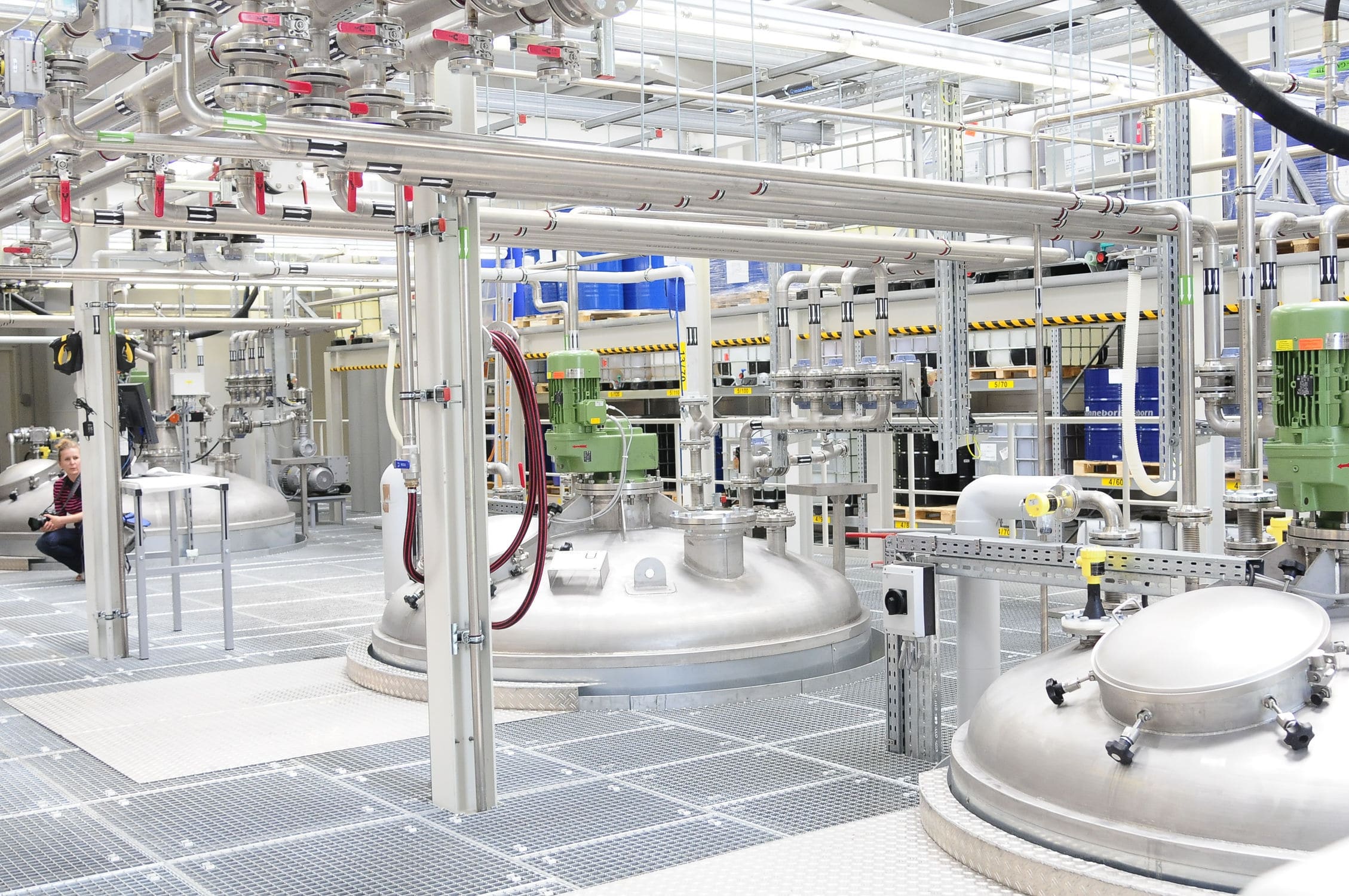


The weighing screw system is composed of a driving part, a double-layer screw stirrer, a U-shaped barrel and a weighing module. The rotation direction pushes the material from both ends to the middle, and the inner screw pushes the material from the middle to both ends. The different angles and directions of the screw belt wind the material in different flow directions, and the material is rapidly mixed through continuous convection circulation and shear mixing. Pneumatic gate valve is set up in the center of the bottom of the horizontal cylinder, and the spiral structure of the outer spiral belt with the rotation direction of the main shaft drives the material inside the cylinder wall to the central outlet. The pneumatic gate valve is designed to control the lead amount of the end feed, so as to reduce the impact of the drop on the batching accuracy and keep the actual batching value within the error range.


 020-34563445
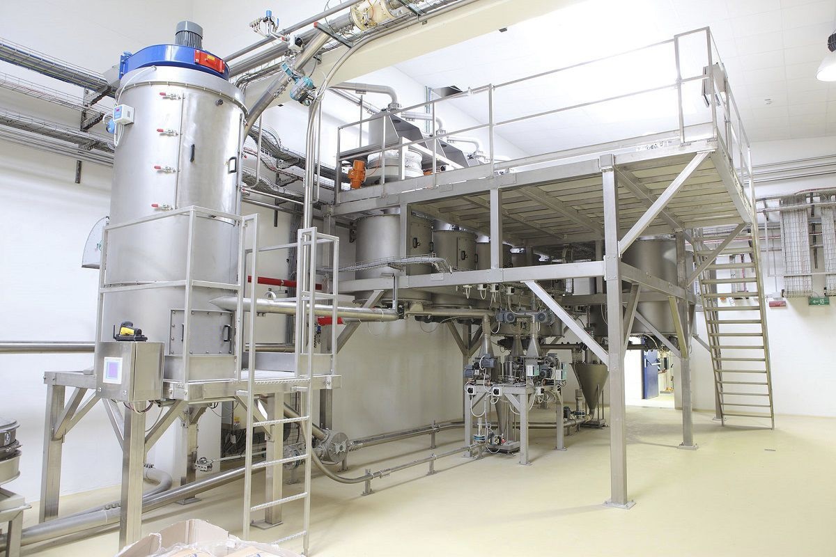
The weighing screw system is a device that integrates feeding and measurement, capable of achieving continuous and dynamic feeding and measurement of granular materials. It adopts the principle of constant-speed quantitative feeding, consisting of a feeding screw, a measuring screw, a weighing sensor, and a control system. It can monitor and adjust the material flow in real time. Based on continuous dynamic feeding and measurement, it adopts the working principle of a constant-speed quantitative feeding scale, integrating the functions of feeding, weighing, and quantitative feeding control into one, forming an integrated mechanical and electrical continuous dynamic feeding and measurement device.
The weighing screw system consists of transmission components, a double-layer screw mixer, a U-shaped barrel body, and a weighing module. The rotating direction of the components pushes the material from both ends towards the center, while the inner screws push the material from the center to both ends. The different angles and directions of the screw belts cause the material to flow in different directions. Through continuous convection and shearing mixing, the material achieves rapid mixing. The bottom center of the horizontal cylinder is equipped with an outlet and a pneumatic valve. The outer spiral belt's helical structure cooperates with the main shaft's rotation direction to drive the material inside the cylinder wall to the central outlet for discharge. The pneumatic valve uses a termination feeding advance amount to control the termination feeding advance amount, reducing the impact of the drop height on the batching accuracy and keeping the actual batching value within the error range.
The weighing control scale system transports piles of materials from the coarse feeding hopper to the hopper scale, where the upper and lower two hoppers of the hopper scale perform interlocking and closing at a certain frequency. The weighing scale separates 90% of the predetermined weight of the material. Then, the weighing screw machine transports the separated material to the Electronic scale, where the electronic scale measures the accurate weight of the material and sends a signal to the control element. The control element receives the signal and analyzes it, then sends a control signal to the fine feeding mechanism to convey the remaining weight of the material to the mixing mechanism. During the transportation process, the electronic scale dynamically measures the weight of the material on the hopper and sends a signal to the control element. When the weight of the material on the hopper reaches the predetermined weight, the control element sends a signal to the motor of the control push plate, which drives the push plate to push the material on the hopper to the mixing mechanism.
The weighing screw machine is transported from the feeding inlet through the screw conveyor to the connected metering electronic scale. The weighing sensor installed on the top of the metering electronic scale detects the weight of the material and generates a voltage signal proportional to the weighing load, which is sent to the controller. Together with the preset electronic scale speed data (during measurement, the metering electronic scale operates at a constant speed, so the speed signal is the design value of the metering electronic scale), it is calculated to obtain the instantaneous flow rate and cumulative weight value. The control system compares the actual flow rate signal with the set flow rate signal, and through PID regulation, outputs control signals to the frequency converter to dynamically adjust the speed of the feeding auger, thereby achieving quantitative feeding.
Due to a certain height difference between the outlet of the feeding drum and the electronic scale platform, the materials in this drop will cause errors. If dynamic control is selected, no matter how the control element sends control signals to the motor of the feeding drum, there will be errors. The control element only sends control signals when the weight of the material on the electronic scale hopper is the same as the predetermined weight, and the feeding drum can stop feeding on time. There is still a continuous flow of material between the surface of the material on the feeding outlet hopper and the hopper scale, which also causes measurement errors. Therefore, the distance between the outlet of the feeding device and the hopper scale should be reduced, and the flow volume during feeding should also be reduced.


