








The hopper screw scale can achieve precise material weighing by controlling the screw rotation speed. This can further improve the weighing accuracy. The prerequisite for improving the weighing accuracy is to enhance the accuracy of controlling the screw number. A toothed belt drive can be adopted. Through the small pulley in a tower-shaped structure and by changing the position of the toothed belt on the pulley, the screw rotation speed can be accurately calculated, and this can further improve the precision.

 020-34563445
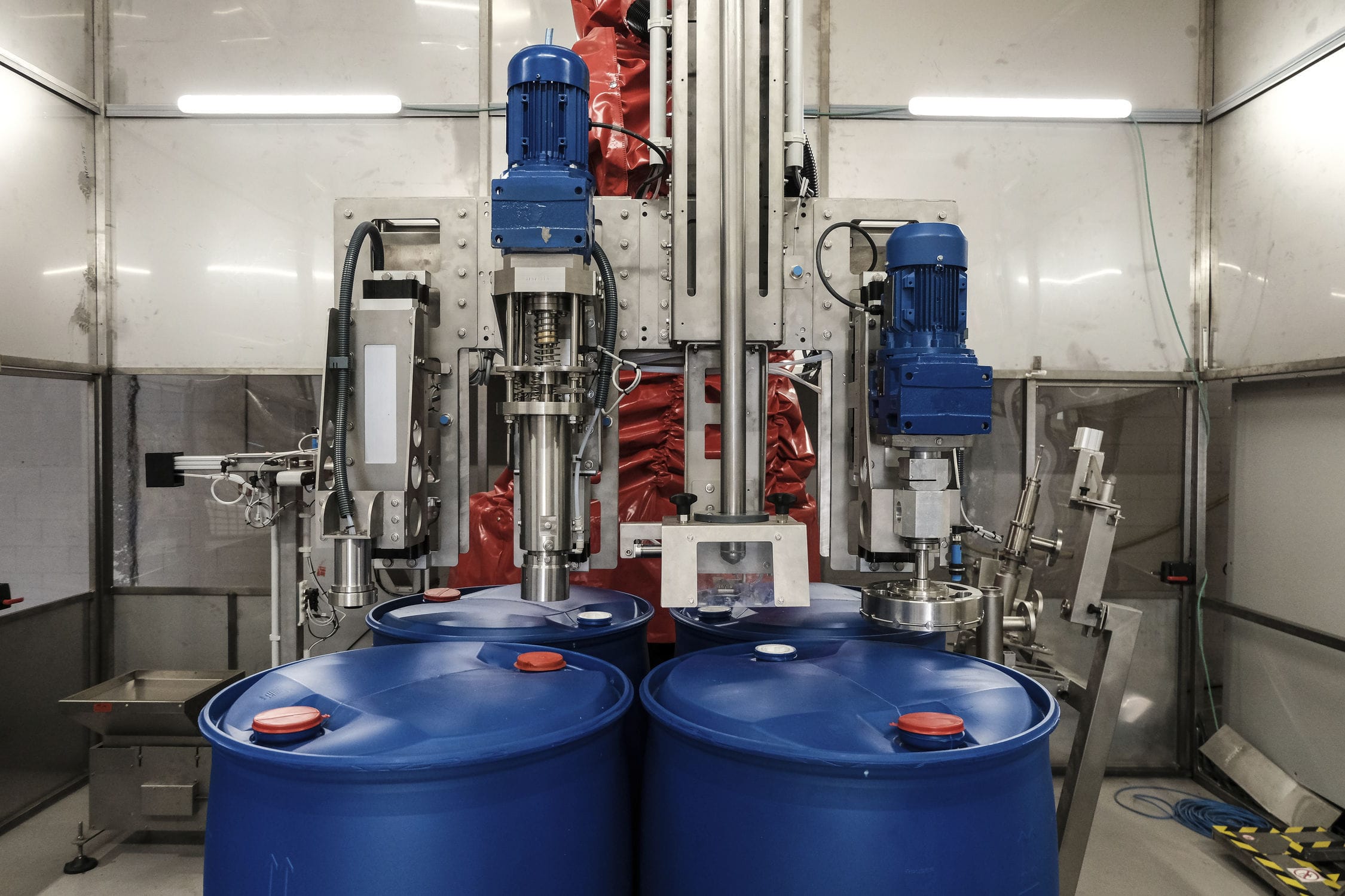
The hopper screw scale can achieve continuous filling of containers and bottles on a rotating worktable. The turntable has multiple workstations, which can realize filling, sealing and other processes. To ensure accurate filling and sealing at these workstations, the Filling machine needs to be equipped with positioning devices. According to the control requirements for filling and sealing stations, the empty bottle station is used to input and output the final filled containers from the station. The empty container bottles are transported by a conveyor belt to a fixed worktable with low surface friction, and then enter the groove of the turntable station by inertia. After that, the turntable rotates and drives the container bottles to stop rotating after entering the station for filling. Then, the turntable rotates and drives the filled container bottles to stop rotating after entering the station for sealing and pressing. Finally, the turntable rotates and drives the processed containers to enter the station, and then automatically outputs and places the processed container bottles through the conveyor belt.
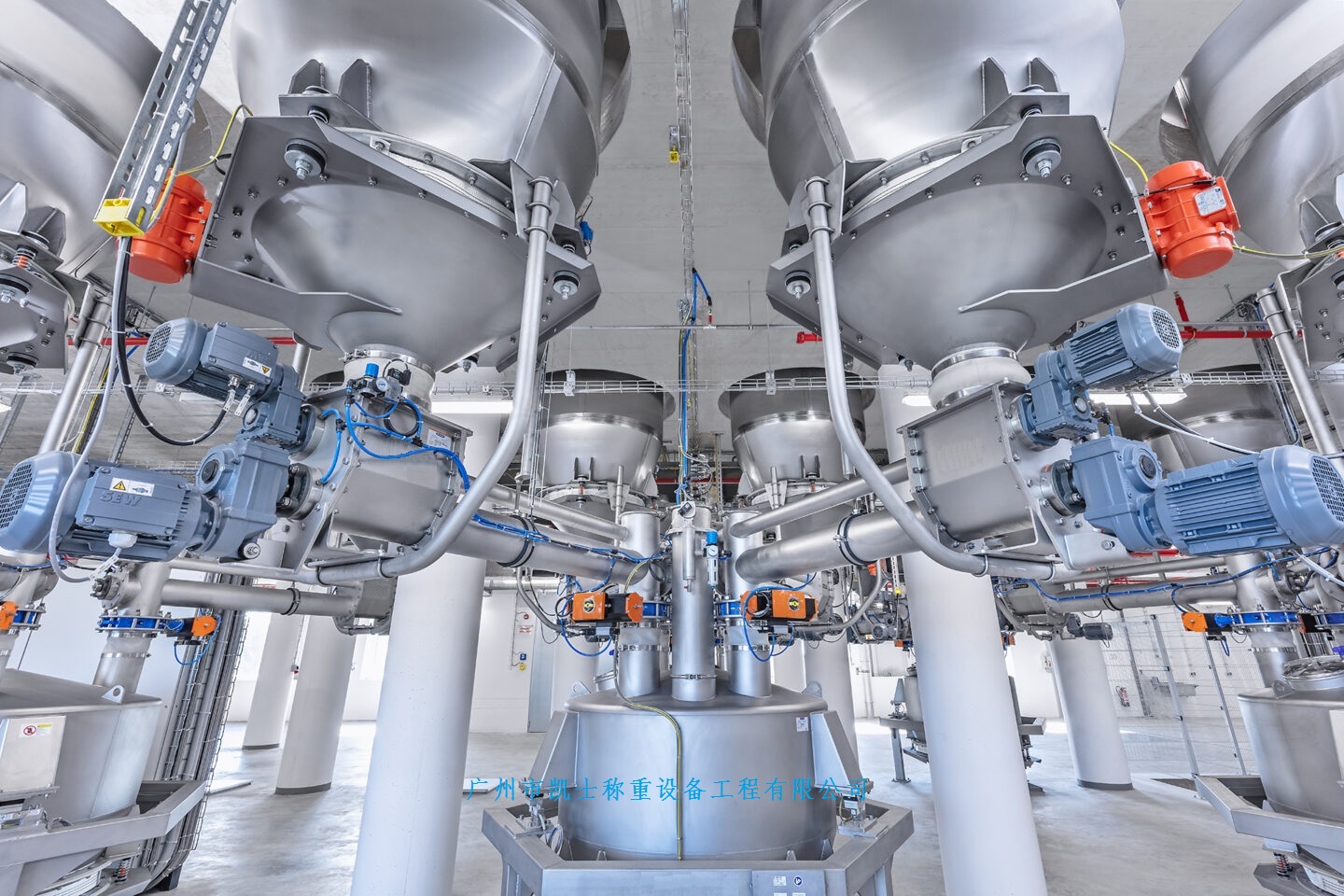
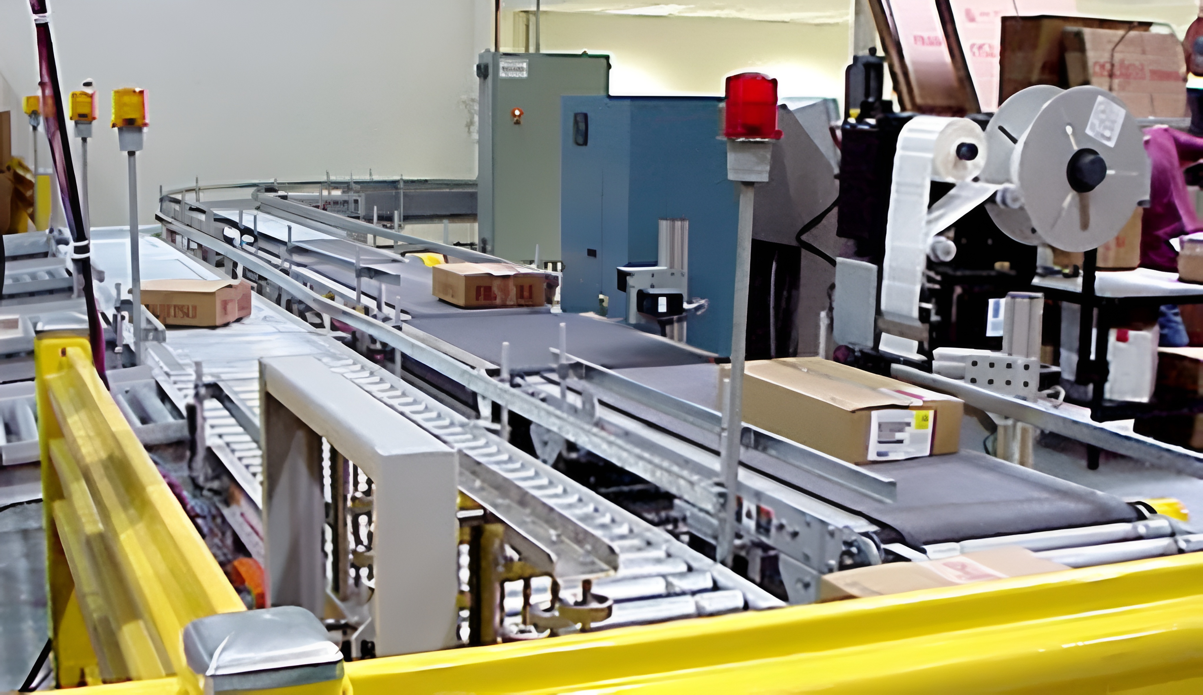
The screw hopper scale uses a conveyor belt for continuous transportation of containers. Container bottles are evenly distributed at equal intervals on the conveyor belt, and after entering each workstation, the predetermined processing steps are completed in sequence. After all processes are completed, the containers are output to the designated position by the conveyor belt. By using motor drive and selecting mechanisms, motion transmission and conversion can be achieved to achieve automation. The Filling system consists of a hopper scale, a bracket, a filling port mechanism, and a motor. The hopper scale is equipped with a weighing module to control the operation of the feeding system. When the material is reduced to a certain position and the filling amount is insufficient, the motor of the feeding system is controlled to start and start conveying the material into the hopper. When the material in the hopper reaches the top position, the weighing sensor controls the feeding motor to turn off and stop feeding. The screw inside the weighing bucket is used for weighing, and a variable frequency motor is used to adjust the filling volume and filling speed by adjusting the speed. The lower part of the hopper scale is supported by a floor bracket, and the control cabinet is fixed on the bracket. The bottom of the bracket is equipped with adjustable feet to adjust the height of the filling port, suitable for filling different heights of tank types.
The hopper scale can achieve accurate weighing of materials by controlling the number of screw rotations, which can further improve the weighing quality. The prerequisite for improving the weighing quality is to improve the accuracy of controlling the number of screws. A toothed belt drive can be used, and by changing the position of the toothed belt on the tower shaped structure of the small pulley, the calculation of the screw rotation speed can be well achieved. In addition, a photoelectric encoder can be equipped on the screw to further improve accuracy. The power of the stirring motor is transmitted to the stirring rod through the transmission mechanism, and the stirring rod can effectively change the stress distribution of the powder, thereby improving the flow state of the powder and achieving the goal of stabilizing the powder packing density, ultimately improving the measurement accuracy. When starting to measure, the measuring motor drives the small pulley to rotate the large pulley, and the photoelectric encoder also starts to rotate. After the electromagnetic clutch receives the signal, the spiral shaft rotates after the clutch and the large pulley are engaged. When the measuring spiral shaft and the photoelectric encoder rotate the set number of turns to meet the requirements, the electrical control system receives the signal, and the large pulley and clutch are disengaged. The brake also brakes, and packaging begins. After packaging is completed, repeat the above actions.
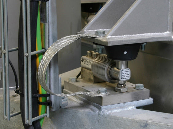
The screw Electronic scale adopts a weighing platform, with a back plate at the top of the weighing platform and a weighing mechanism at the top. The weighing mechanism uses two mounting plates, both of which are fixedly installed on the front of the back plate. The top of the weighing platform rotates and is equipped with two screw rods that pass through the mounting plate at one end. The outer surfaces of the two screw rods are connected to a motor component, and the outer surfaces of the two screw rods are equipped with connectors. A sealing frame is fixedly installed on the opposite side of the two connectors, and a pneumatic butterfly valve is set inside the sealing frame. The top of the weighing platform is equipped with a driving structure. The driving structure adopts a motor, which is fixedly installed on the top of the weighing platform. The outer surface of the motor is fixedly installed with a mounting bracket. The left side of the motor is fixedly connected with a transmission component, and the outer surface of the left screw is fixedly installed with a second bevel gear. The front of the screw electronic scale is fixedly installed with a silo, and the back plate is fixedly installed on the top of the weighing platform. A limit strip with a connecting block and a sliding connection on the back of the connecting block is used. The connecting block is threaded to the outer surface of the screw rod and is fixedly connected to the outer surface of the sealing frame on one side. The limit strip is fixedly installed on the front of the back plate. The screw weighing adopts a hot melt strip with two electric push rods and two electric push rods fixedly connected on the opposite side. The two electric push rods are fixedly installed on the left and right side walls of the inner cavity of the sealing frame. The outer surfaces of the two electric push rods are both fitted with installation rings, which are fixedly installed on the rear wall of the inner cavity of the sealing frame. The weighing screw adopts a weighing plate with a protective compartment and a sliding connection on the inner wall of the protective compartment. A weighing module is fixedly installed between the bottom of the weighing plate and the bottom wall of the protective compartment. The protective compartment is fixedly installed on the top of the weighing platform. The output shaft of the motor is fixedly connected to the shaft through a coupling. A support plate with an outer ring and fixed connections on both sides of the outer ring is used. The support plate is fixedly installed on the top of the weighing platform, and the outer ring is fixedly installed on the outer surface of the motor.