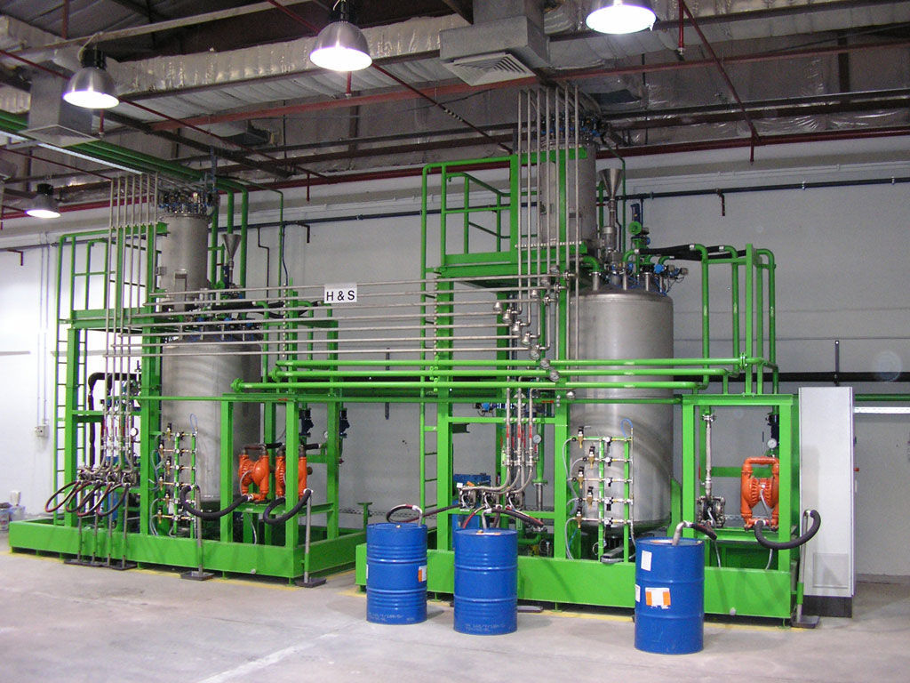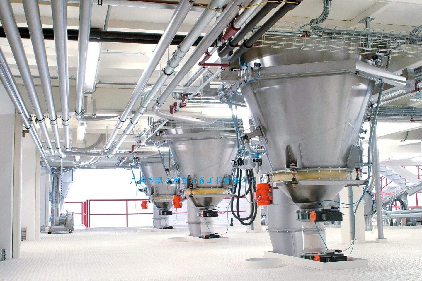


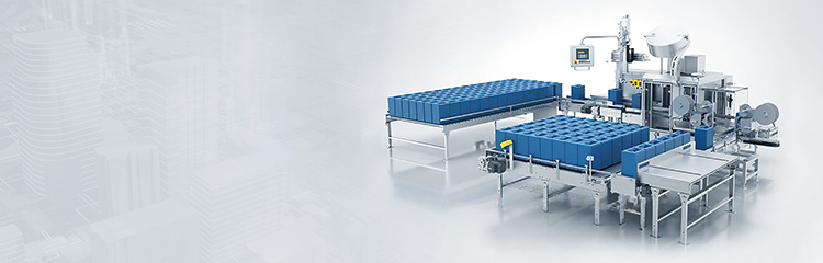


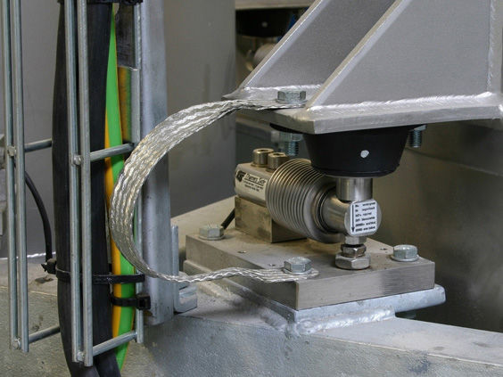
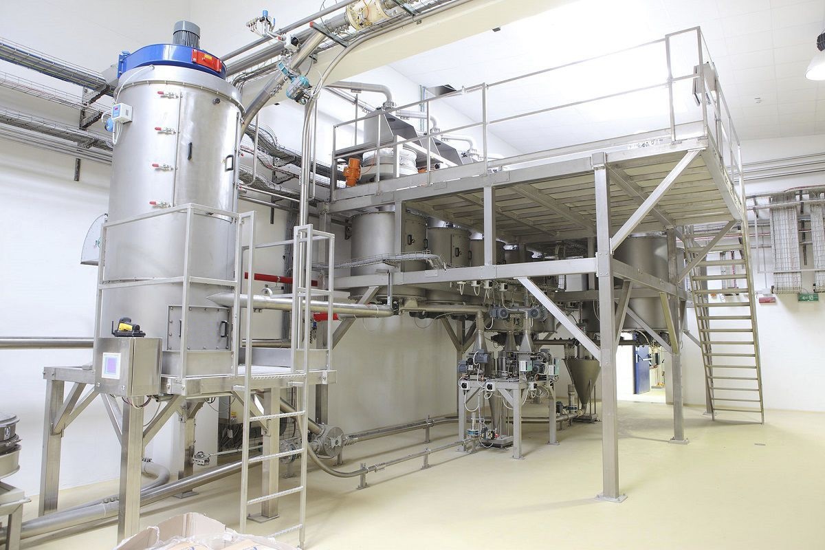
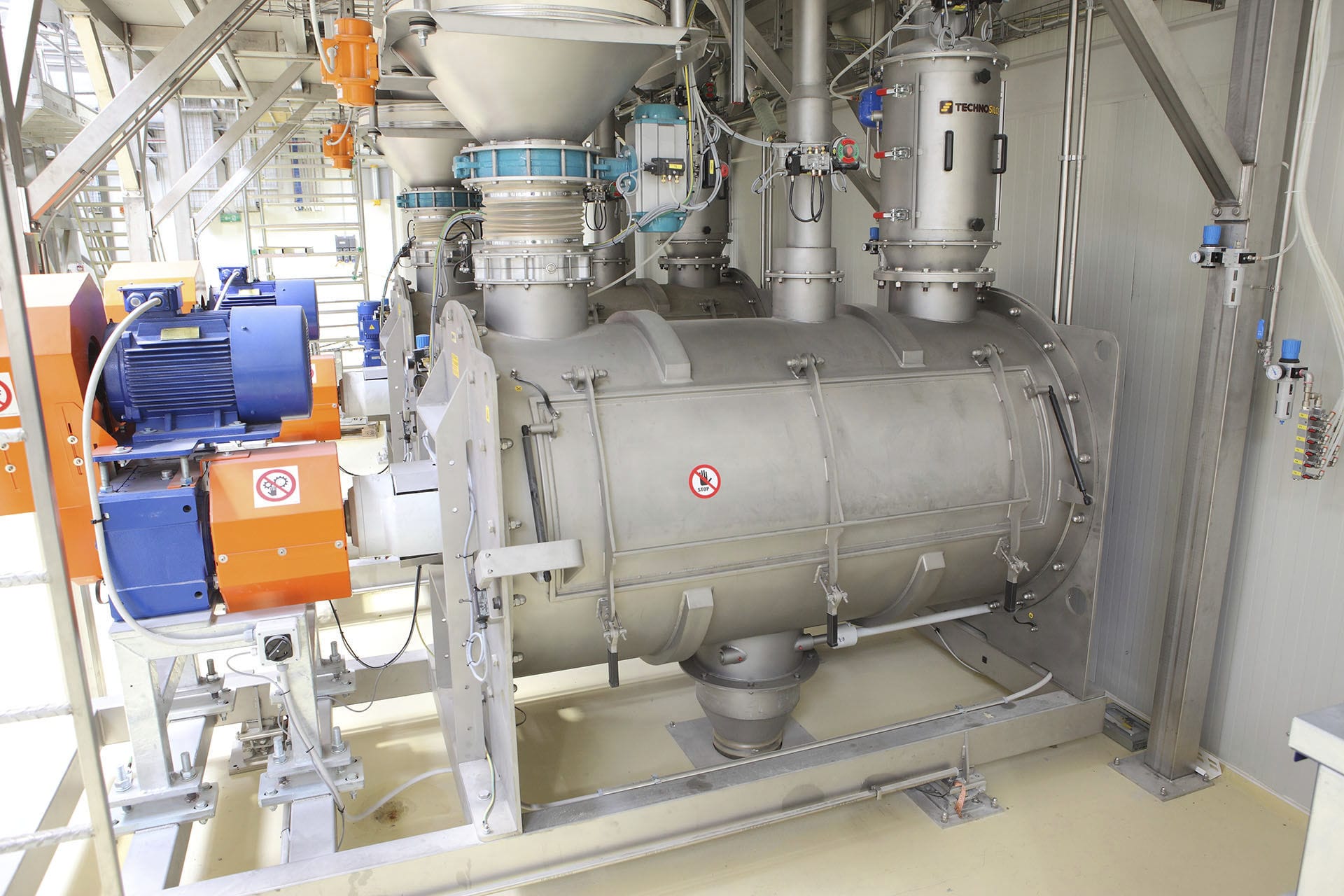
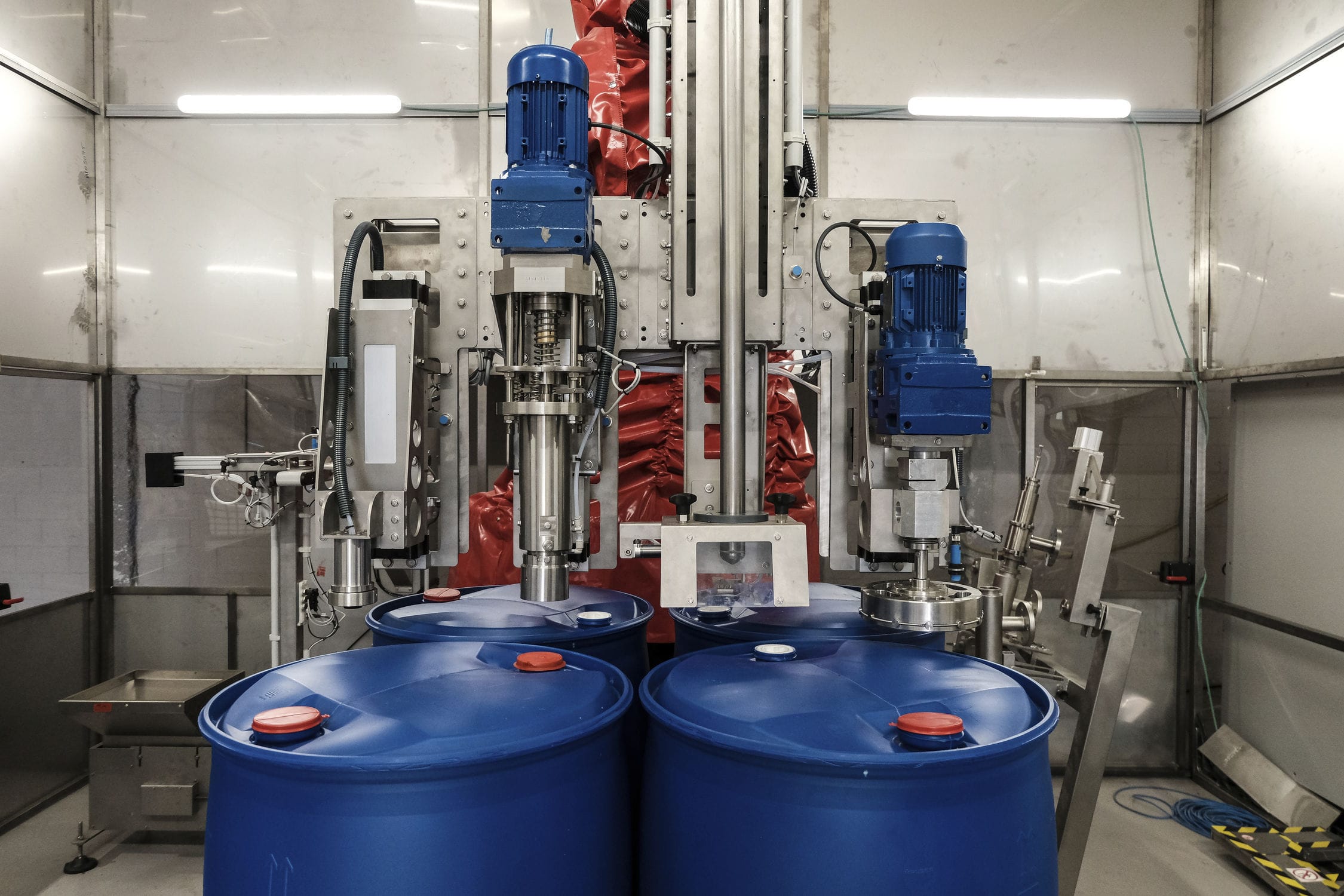


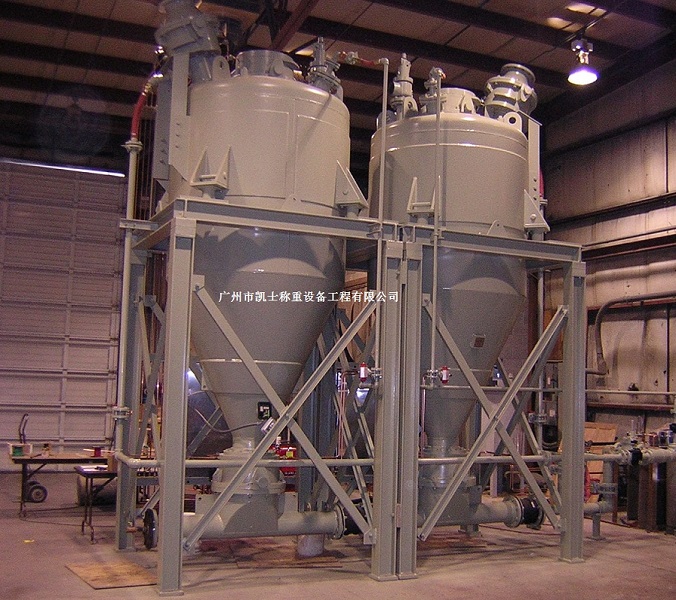
The weight reducer consists of three parts: the feed conveyor, the hopper, and the discharge conveyor. The PLC detects the state of the discharge screw. When the discharge screw is activated by other production equipment, the feed conveyor is driven by the PLC to feed materials into the weighing hopper. The hopper is supported on the weighing module. The weighing instrument transmits the weighing data through the COM port to the PLC. When the predetermined weight is reached, the PLC stops the feed screw and, after the data stabilizes, the PLC adds the weight data, along with time, record number, etc., to the memory unit and adds it to the cumulative quantity to obtain a new cumulative quantity.

 020-34563445
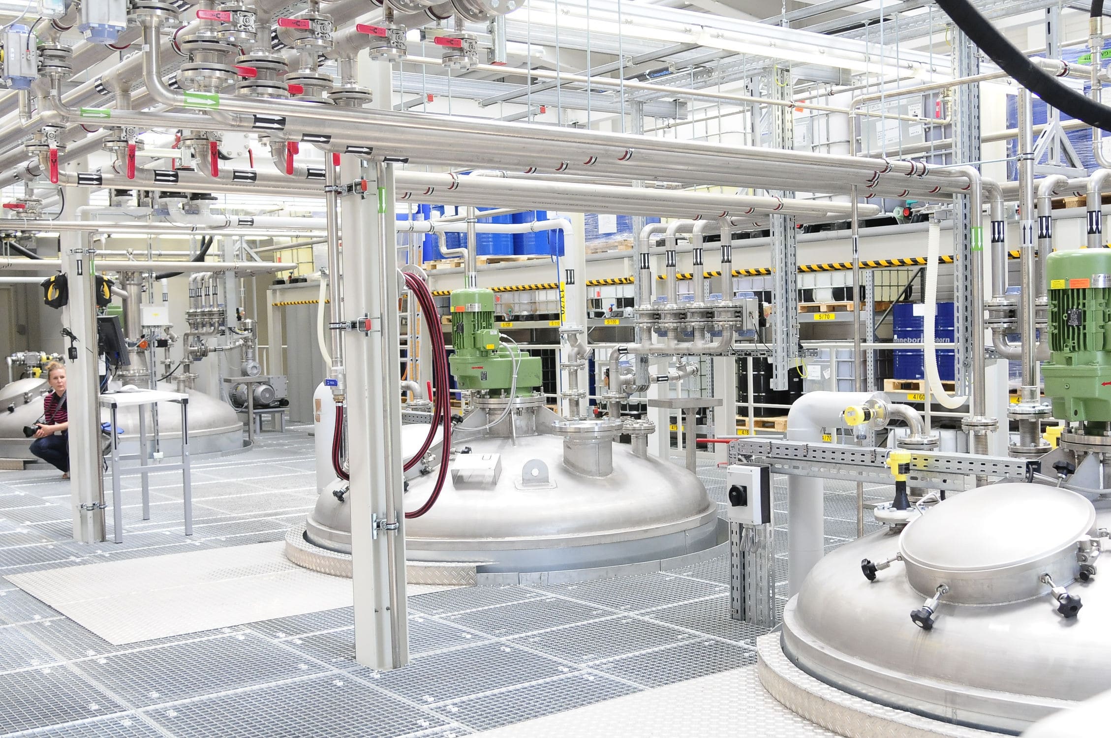
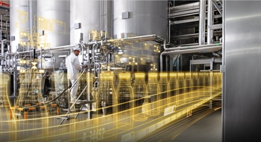
The reduction material hopper scale can enable two or more different substances to be dispersed and mixed with each other, thereby achieving uniform mixing and weighing of the ingredients. It can also accelerate the heat and mass transfer processes. When the Electronic scale is activated during production, the PLC sends a dynamic measurement start signal to the measurement instrument, and the instrument then begins to collect and display the weights of each stage, and adopts fast feeding and slow feeding strategies at different weight stages to balance efficiency and measurement accuracy. When the target value is reached, a stop measurement signal is output, and the PLC controls to close the relevant valves and pumps of the reactor and other components. At the same time, the discharging action to the reaction tank is completed, and the measurement instrument automatically clears and resets the weight. The Weighing system starts from the raw material feeding pump and continues until qualified materials are sent to the storage tank. This includes the control and interlock of all feeding and discharging valves, the start and stop of each material feeding pump, the control of fast and slow feeding, status detection, and all data processing functions. The batching control system consists of the weighing unit, data processing unit, and logic control unit. At the end of batching, the upper computer (PC) stores the actual data of this batch and can perform certain precision analysis as required, generate various reports, and be used for production statistics and management. According to user requirements, various required reports can be printed online or offline, such as the daily production output of the reaction tank, raw material consumption, raw material inventory, and finished product inventory, etc.
The automatic hopper weighing system is composed of a feeding screw, weighing instrument, vibrating Feeder, PLC, touch screen and multiple control cylinders, etc. It is divided into two major parts: mechanical and control. It consists of three parts: the feeding conveyor, the hopper and the discharging conveyor. The PLC detects the state of the discharging screw. When the discharging screw is started by other production equipment, the feeding conveyor is driven by the PLC to feed materials into the weighing hopper. The hopper is supported on the weighing module. The weighing instrument transmits weighing data through the COM port to the PLC. When the predetermined weight is reached, the PLC stops the feeding screw, and after the data stabilizes, the PLC will add the weight data, time, record number and other information to the memory unit and add it to the cumulative quantity to obtain a new cumulative quantity. At the same time, it outputs to drive the printing, control the opening of the hopper door of the weighing cylinder, and the materials enter the Feeding machine. When the weight is lower than the set zeroing value, the hopper door is closed, and the base number is cached. In the next process, it is deducted to ensure the accuracy of the cumulative weight. One feeding process is completed.
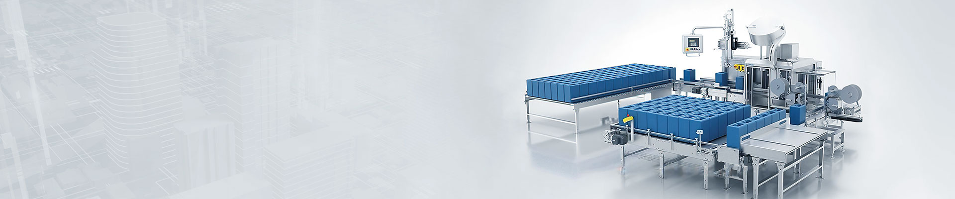
The hopper scale automatically adds two or more types of materials to the mixing machine in a certain proportion and quantity, and then discharges the materials automatically after they have been mixed to meet the predetermined requirements. During the operation, the screw feeder is started first, and materials are continuously added at full speed. The electronic scale continuously weighs. When the weight reaches a certain value, the speed of the screw feeder begins to decrease (through frequency conversion speed regulation), and as the amount of materials increases, the speed of the screw feeder becomes slower. When the weighing value approaches or reaches the required value, the screw feeder stops, and this type of material weighing is completed. The electronic scale discharge valve is opened to temporarily store the materials in the storage bin, and then the second feeding machine is started to weigh the second type of material and perform feeding control in the same way as before. After weighing, the material is also placed in the intermediate storage bin for temporary storage. Frequency converter control mainly includes automatic start-stop control and speed regulation. To achieve automatic weighing, it is necessary to realize the automatic operation of material transmission and automatic speed regulation. Automatic operation means that the motor starts and runs automatically and stops automatically. The output signal triggers the external intermediate relay to control the main circuit operation.