


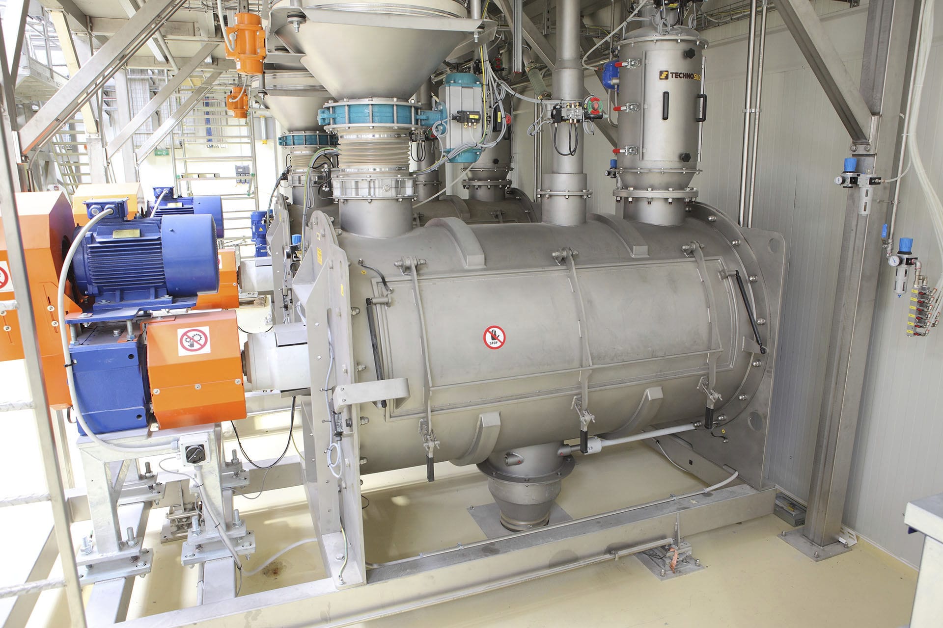


The liquid hydrochloric acid filling and filling machine uses motor, reducer and gears as power transmission components to drive the container to perform fixed-point filling, achieving the quantitative filling of the liquid. The reducer is driven by a V-belt, and then the gear at the output end of the reducer drives the large gear to rotate. The liquid in the storage tank is filled into the filling gun through the holes on the liquid valve body. The air inside the gun is discharged through the air pipe. When the container rises along with the bucket support, the bucket mouth presses the fixed cover, causing the valve core to rise as well. When it reaches a certain position, the hole on the liquid inlet valve body closes, isolating the liquid in the filling gun from that in the storage tank. At the same time, the hole on the valve core opens, allowing the liquid in the filling gun to flow through this hole into the filling gun. Thus, the next filling cycle begins.

 020-34563445
The liquid hydrochloric acid filling and packaging machine has both switch quantity control and analog variable frequency speed regulation control. The equipment can operate automatically continuously, and each moving point can also be operated manually by point control. Thus, there are many input points corresponding to various operations and output points for displaying the required action status information. A scheme combining PLC and touch screen is adopted. The analog input points of the variable frequency speed regulation system and one analog output point are used. The speed measuring motor measures the motor's speed, and the voltage value signal is connected to the analog input point. After comparison with the given value and PID calculation, the calculation result is output from the analog output point and serves as the control signal for the frequency converter to achieve variable frequency speed regulation. The analog input points of the variable frequency speed regulation system and one analog output point, the speed measuring motor measures the motor's speed, and the voltage value signal is connected to the analog input point. After comparison with the given value and PID calculation, the calculation result is output from the analog output point and serves as the control signal for the frequency converter to achieve variable frequency speed regulation.
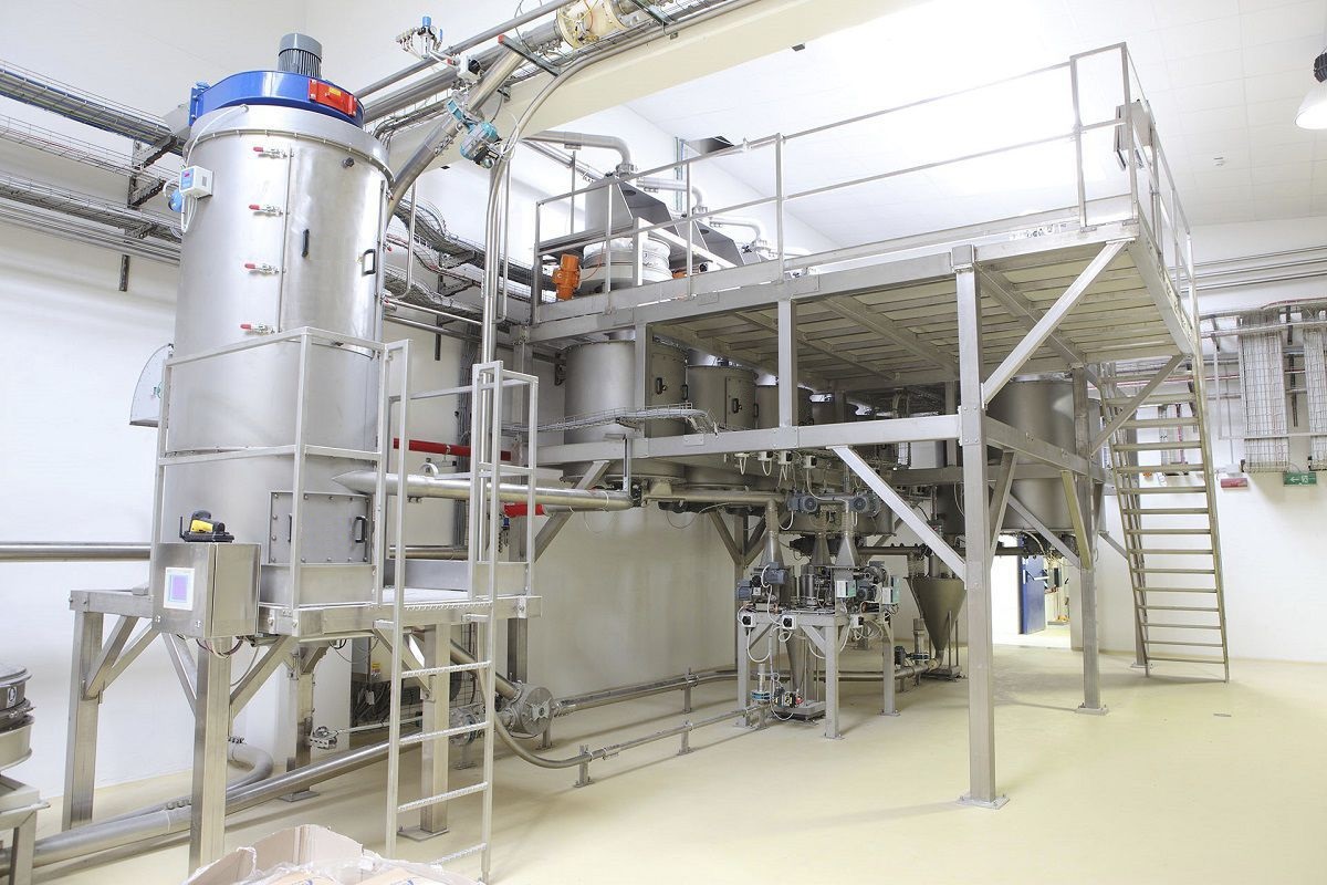
The structure of the automatic Filling machine includes the frame and protective cover, which support various components and serve as protective and decorative elements. The filling machine frame, cover, guard plates, etc. form the assembly. The transmission power comes from the motor, reducer, and gears that drive the containers to be filled at a fixed point, completing the quantitative filling of liquids. The control of the filling machine and the bucket conveyor is achieved through control valves such as storage tanks, float-type liquid level control valves, and filling valves. The transmission is driven by a belt, which is then driven by the output gear of the reducer, and in turn, the large gear rotates. The middle pillar of the drum and the storage tank rotate together. When the container is placed on the Electronic scale bucket support, due to the rollers at the lower end of the bucket support rolling on the fixed cam, the bucket support carries the container for transmission. The liquid in the storage tank is filled into the filling gun through the holes on the liquid valve body, and the air inside the gun is discharged through the air pipe. As the container rises along with the bucket support, the bucket mouth presses against the fixed cover, causing the valve core to rise as well. When it reaches a certain position, the hole on the filling valve body closes, isolating the liquid in the filling gun from the liquid in the storage tank. At the same time, the hole on the valve core opens, allowing the liquid in the filling gun to flow through this hole into the filling gun. Thus, the next filling cycle begins.
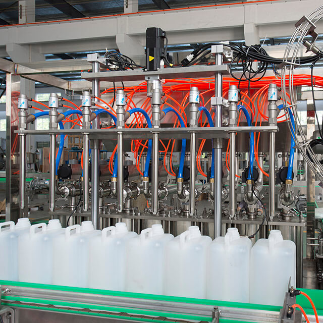
The Liquid filling machine converts the measured weight parameters into analog voltage or analog current by an electronic scale, and simultaneously detects the speed of the pipeline transportation through the electronic scale, which is then transmitted to the weighing instrument. The digital signal converted by the weighing instrument is sent to the PLC, and through the weighing instrument, the set filling volume and the weight of the material are calculated and displayed. The measurement signal is transmitted through the current isolation module to the control system to complete the weighing display and production process control filling process. The electrical control system consists of the main control console, frequency converter cabinet, PLC host, detection device and drive device. The main control console adopts a technologically advanced and reliable programmable PLC, along with electronic scale position sensors and other detection devices, and drives rollers and filling guns, etc. The drive components use high-performance frequency converters to control the motor, completing various functions such as filling, discharging, soft start, soft stop, speed adjustment, etc. It is equipped with status display. One electronic scale is installed under each conveyor belt, and when the material on a certain conveyor belt exceeds the limit value, the corresponding switch closes to provide a signal to the PLC through the program analysis for filling processing and display of the target volume status. On the left and right of the conveyor, position switches are installed. Once the conveyor deviates, the position switch will close, and through PLC analysis, the filling device of the filling gun is driven for automatic control. A certain height detection device is installed on the conveyor to collect the fallen dripping materials. The filling gun retracts to its position and the air cylinder switch is opened, and through PLC drive, the dripping treatment is carried out. When the Weighing system is working, the coarse and fine filling mechanisms add materials simultaneously. According to the output signal of the electronic scale, the PLC control system controls them respectively according to the set weighing value. When the electronic scale weighs a certain amount, the coarse filling mechanism stops adding materials, and the fine filling mechanism continues to add materials until the system set value is reached and stops. The leakage mechanism material cylinder will pour the material into the receiving pipeline to complete a qualified weighing process.


