


 2020.01.19


Summary:An industrial online sorting machine based on machine vision with high-speed linear array charge-coupled device (CCD) and digital signal processor (DSP) as the core.The system consists of two parts: hardware and software. The hardware part includes optical imaging module, image acquisition module, data processing module and interface module. The software part includes the driver, system configuration program, image preprocessing and data processing program of each part.
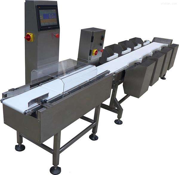
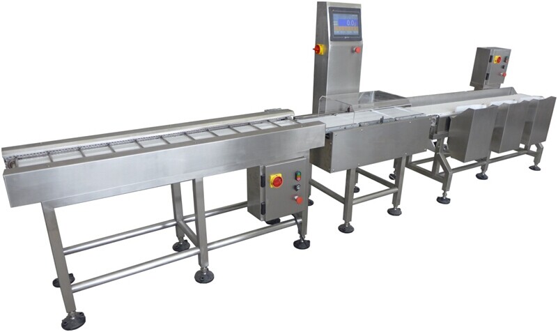
Industrial online vision sorting scale, an emerging online inspection means in recent years, is based on machine vision and utilizes an intelligent image acquisition and processing system to collect and process the surface image signal of the inspection target and output the processing results. Compared with other machine vision equipment, the most significant feature of industrial online checkweigher is that it has strong real-time to match the high-speed production line.
At present, there are two main forms of machine vision products in:
(1) PC-based board and card type, the use of image acquisition cards and image sensors on the PC. The way with the help of the PC's versatility, low development difficulty, but high operational difficulty and poor stability, and the existing operating system are non-real-time systems, real-time is difficult to ensure, in addition such systems are high cost, large size, poor portability.
(2) Embedded, embedded processor as the core, the overall development, including hardware circuits, device drivers and algorithms, software and other complete systems, so hardware and software can be flexibly configured, small size, conducive to the realization of high-speed data acquisition and processing, real-time is good, and is more suitable for online inspection.
At present, the main international machine vision product manufacturers have their own embedded vision inspection products. In China, the field of machine vision due to the late start, self-developed products are almost all board and card type, and embedded vision inspection machine is not yet a mature product. For this reason, the author's laboratory after a year of research, the embedded processor and image acquisition system successfully combined to develop a set of machine vision-based embedded industrial online checkweigher that can meet the higher speed production line.
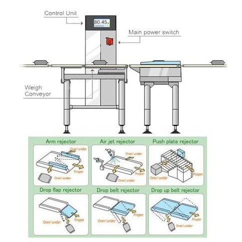
The conveyor system takes line array CCD and DSP as the core, real-time acquisition of detection object image signals, digitized and processed by the processor, and outputs the processed results in the form of pictures or signals. In addition, the system can also realize online parameter configuration through external interface.
2 system hardware design
The industrial online visual inspection smart camera system includes the following four parts.
(1) Optical imaging module, which provides effective light conditions and optical images for the CCD sensor, consists of a light source and an optical lens. Depending on the detection object, the light source can be DC, AC or pulse. If non-DC mode is used, the light flashing frequency needs to be synchronized with the CCD exposure time in order to avoid stroboscopic effects on signal acquisition.
(2) data acquisition module, composed of line array CCD, CCD drive signal enhancement circuit, CPLD and A/D, used to collect image signals and digitize analog signals for DSP processing. The system uses black and white high-speed line array CCD - TH7814A, the CCD is a dual output, the effective pixel 2048, like the sensitive unit size of 7μm, the highest drive frequency of 50MHz; CCD drive signal enhancement circuit is designed to meet the CCD required 9V high-speed drive; A/D chip using two XRD9856, the chip's maximum sampling frequency of 27MHz. With correlation double sampling function (CDS), accuracy of 10 bits; the above devices synchronized drive pulse are generated by the CPLD.
(3) data processing module, composed of DSP, random memory (RAM), read-only memory (ROM), to complete the data processing and storage, system startup and other functions.DSP using TI high-speed multimedia processor TMS320DM642, operating frequency 600MHz, the highest instruction processing speed of 4800MI/s, data bus width of 64 bits, the processor's most important feature is that with three-way video interface, can be used in a variety of ways. The processor's most important feature is that it has a three-way video interface, which can directly input and output up to 80MHz BT.656, Y/C video, original video and other formats of video signals, this system uses the original video mode.RAM capacity of 32MB, the data width of 64-bit SDRAM; ROM by the capacity of 16MB of FLASH and 256B of EEPROM.
(4) system interface module, the system provides the interface 100Mb / s network interface (TCP / IP protocol), serial peripheral interface (SPI), RS232 serial interface for sending and receiving various data and control signals.
The system workflow is as follows: light source irradiation to the detected object, the detected object through the optical lens imaging in the CCD image-sensitive surface, through the CCD drive circuit to produce the drive signal derived from the CCD original image signal, the signal by the back stage of the AD converted to digital signals into the DSP. at this time, two types of data processing:
(1) the data will be processed directly for arithmetic processing, only the results required after processing from the specified interface output, such as to the back stage of the sorting mechanism;
(2) Keep the data in its original state or output it in picture format after processing.
3 System program design
3.1 System Driver
3.1.1 CPLD hardware program design
The role of the CPLD is to generate CCD, A/D and DSP video port synchronization drive pulse. From the working principle of this CCD and A/D! -4 it can be seen that the CCD and A/D drive signal timing, and only so that the A/D's SHP and SHD are sampled at the dark level and effective level position of the CCD output signal, respectively, in order to accurately capture and convert the original analog signal generated by the CCD into a digital signal, in addition, the DSP video interface also needs the synchronization pulse and synchronization signal generated by the CPLD to receive digital image signals, the driver is written in VHDL.
3.1.2 DSP Hardware Driver
The DSP hardware driver is used to manage the working mode of each part of the hardware and specify the data flow and organization, which consists of the following five parts:
(1) Video port configuration program. As the CCD has a dual output, using two pieces of A/D, the data for the two 10-bit raw video data, so the video port is configured as a dual 10-bit raw video data capture mode, and set up a 512B first-in-first-out cache (FIFO) for each video interface. When the system works, the captured digital video data is put into the FIFO, and when the FIFO is filled, the data is transferred through EDMA channel and refilled after the data is cleared. The video interface operating frequency is the same as the front-end CCD drive frequency.
(2) Data transfer channel configuration. Image data usually have a large amount of data, so data transfer, handling and organization is an important part. Data transfer in this system uses enhanced direct memory access mode (EDMA). When the FIFO is full, EDMA is triggered to start, and the data is transported to RAM in one go, and the data organization is kept unchanged. the FIFO is emptied and then filled again. This is repeated until a stop signal is received. The system EDMA configuration using block synchronized 2D to 2D mode (blocksynchronized2D-to-2Dtransfers).
(3) interface driver. 100Mb/s network interface can be used to transmit image data due to the faster speed, but also can receive control signals. RS232 and SPI interfaces are used to receive system control signals or send out the processing results signal.
(4) External synchronization signal configuration for synchronization with pulse light source or back stage actuator.
(5) System self-guidance program, program size of 1KB, stored in FLASH from 0KB to 1KB space, used to guide the system startup in the offline situation, so that it can work independently.
3.2 System Software Design
3.2.1 System control software
The testing machine is a general-purpose system, the environment and testing objects vary greatly, so it needs to be configured according to the specific environment and testing content. Usually the program debugging of embedded systems need to use an emulator, can only modify the program code, time-consuming and inconvenient to use, so the system designed a set of programs that can be configured online through the network interface. This only requires an ordinary network cable to connect the checkweigher to the computer, using the program can easily configure the system parameters and real-time viewing of the image. Configuration content includes the camera IP address and port number, SPI configuration and output, UART configuration, image width and gain and other attributes, the camera exposure time and other parameters and related image storage and other operations and display the image.
3.2.2 Image pre-processing
(1) Aberration correction
Aberration is a type of aberration, caused by the optics, and is the difference between the actual imaging height of the off-axis point on the image plane and the ideal image height. For the line array CCD system, the aberration caused by the optical lens exists only in the direction of the image width. In the more stringent requirements for the size of the inspection accuracy of the application, this aberration is not allowed to exist, must be corrected.
Currently used image aberration correction methods are mainly two: fitting the lens aberration curve "and the use of standard samples! The former need to know the design parameters of the optical system, the latter only according to the system aberration characteristics of the correction, the method is simple, so this system uses the latter.
Sample calibration method is the use of customized standard sample, so that it is to be corrected through the optical system imaging, recording the aberration image, and then according to the sample of the ideal design parameters and optical system magnification, calculate the sample of the ideal distortion-free image, compared with the actual image of the difference between the aberration function of the system relationship. Since the system is a line-scan imaging system, the method in the literature [7] is used for correction.
There are two main methods of image aberration correction commonly used a few days ago: fitting lens aberration curves" and utilizing standard samples! The former needs to know the design parameters of the optical system, and the latter only needs to be corrected according to the system aberration characteristics, which is a simple method, so the system adopts the latter.
Sample calibration method is the use of customized standard sample, so that it is to be corrected through the optical system imaging, recording the aberration image, and then according to the sample of the ideal design parameters and optical system magnification, calculate the sample of the ideal distortion-free image, compared with the actual image of the difference between the aberration function of the system relationship. Since the system is a line-scan imaging system, the method in the literature was used for calibration. The experiments were performed using a Wind Phoenix 24mm/2.8 wide-angle lens with a focal length of 24mm, a field of view of 28°, a field of view width of 240mm, and a resolution of 0.2mm.
(1) is the fitting equation
(2) gray scale correction
Industrial online machine vision inspection machine usually work at a higher frequency, generally 2MHz ~ 20MHz, making the exposure time of the line array CCD is only 0.1ms ~ 1ms, so the image surface illumination inconsistency caused by the uneven gray scale of imaging is also a problem that must be solved. For the line scanning system a frame image only one line of the situation, references, and combined with the real-time requirements of the system, the use of relative grayscale calculation method, that is, the first acquisition of the background image signal without detection of the object, and then the acquisition of image signals containing the target object, the two images can be subtracted from the target image of the real grayscale.
3.2.3 Image Detection Program
For industrial on-line machine vision weighing conveyor, the detection content is generally the target's two-dimensional features four, such as color, shape of the outer contour, size in a particular direction, surface finish, surface feature recognition, feature point localization, etc., so the most commonly used image processing is mainly image enhancement, including edge sharpening, contour extraction, histogram processing, Fourier Transform and so on.
In addition to the use of appropriate algorithms for effective processing of the captured image, industrial online sorting scale must also meet the requirements of real-time, so the algorithm program needs to be optimized to give full play to the computing power of the DSP. DSP is a device with parallel instruction execution function, the DM642 used in this system can be executed in parallel in one instruction cycle 8 instructions. The purpose of optimization is to reduce the correlation between program statements, more in parallel to be executed, to give full play to the computing power of the DSP. In addition, when the optimized design of the system using C language still cannot meet the requirements, it is necessary to use linear assembly programming for the core program, which is mainly a loop body with a large amount of operation.
For this reason, the algorithm of this system adopts high-level language and linear assembly language mixed programming, the algorithm program in the main arithmetic process statements in assembly language to improve the speed of operation, and for the data control part of the high-level language to simplify the program, at the same time, the high-level language program is also in accordance with the DSP arithmetic flow for the optimization of the 0: level.
4 Experimental results and analysis
For the system in the experiment and the actual work on the production line of the pictures collected. For the tablet detection in the tablet packaging production line, the detection content is to see whether the tablet is packed into the package and whether the tablet is broken. The tablet packaging equipment operates at a speed of 2 m/s. For rice grain detection, rice grains with abnormal color are detected in a stream of rice grains falling at high speed and the percentage is calculated. The detection speed of the system is 3ms. for the photo paper defect detection in the laboratory, the target moving speed is 1.5m/s. The system can truly capture the high-speed production line with the detection of the target image, and the image grayscale uniformity, basically no aberration, the details are clear, and fully able to meet the requirements of image processing.
In the optimized FFT program for the system computing speed test, the test object for the 1024x1024 black and white images, the running time of 14ms. but this test is only the ideal situation, in the actual system, to assess whether the system can meet the real-time requirements of the detection of the program itself in addition to consider the amount of computation, there is another factor that must be taken into account is the interruptions occurring every second. The number of interrupts per second. The appearance of interrupts interrupts the processing of the program, plus the fact that the execution of an interrupt requires a series of procedures to protect and restore the current process, all of which makes the interrupt handling much less efficient compared to the computational program. The relationship between the number of interrupts per second and the arithmetic efficiency is given, and it can be seen that when the interrupts are increased in a large number, the arithmetic efficiency will be reduced dramatically as a result.
Therefore, in practical use, we should fully understand the characteristics of the detection object and the execution mode of the back-end actuator, so that the simplest algorithm can be used under the condition of meeting the detection accuracy and applying the signal input and output mode that requires the least number of interruptions, and give full play to the efficiency of the sorting machine.
5 Conclusion
The system has the advantages of low cost, small size, fast detection speed, high precision, convenient configuration, etc., which is very suitable for the online detection of industrial production lines, and this is a useful attempt to change the current industrial online machine vision inspection field mainly rely on imported situation. In the future, in order to further improve the detection speed and accuracy, higher speed sensors can be used, and the software algorithm can be changed to hardware realization in order to make the system more perfect.