

 2020.04.01


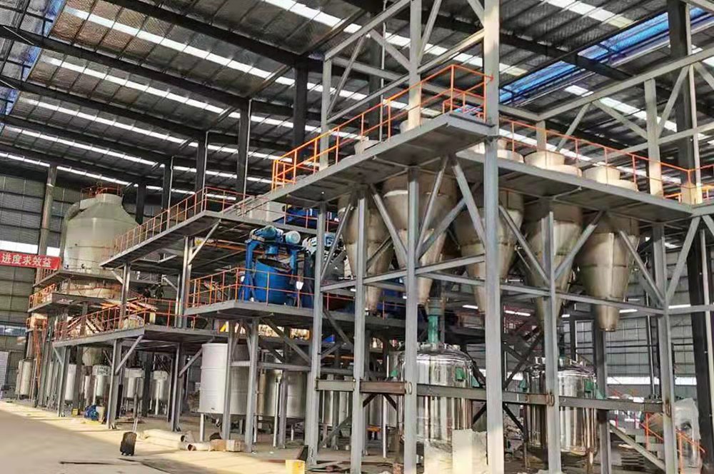
Summary:The data of the batching system are stored in the industrial computer database of the control center. The batching process is monitored by the configuration software, and the weighing control system implements process operations through the control interface.
The working principle and basic composition of loss-in-weight scale
Working Principle of Loss-in-Weight Scale
Continuous loss-in-weight scale is designed according to the principle of controlling weight loss at work. The weight of materials in the loader is converted into analog quantity through load cell and weighing instrument and sent to the programmable controller, which compares and judges the calculated weight of materials with the set upper and lower limit values of weight and feeds intermittently to the loader through controlling feeding device; at the same time, the actual discharge rate (discharge rate) (the rate of discharge of materials) is calculated by the programmable controller and the actual weight of materials is calculated. At the same time, the programmable controller compares the calculated actual discharging rate (discharging capacity) with the set discharging rate, and controls the frequency converter through internal PID adjustment to control the discharging device, so that the actual discharging rate accurately tracks the set value. When the feeding device is turned on to feed the loader, the control signal locks the discharge rate for volumetric discharge. The HMI displays the actual discharge rate and the cumulative weight of material discharged. The dosage data are stored in the database of the industrial computer in the control center, and the dosage process is monitored by the configuration software and operated through the control interface.
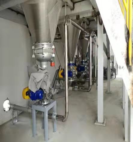
Loss-in-weight weighing equipment composition
Loss-in-weight scales are mainly composed of a feeding device, a weighing module and a weight display controller for the discharge device.
Feeding device
The feeding device is used to control the fast feeding of the weighing sensor, and adopts the form of round arc door, which has the advantages of strong sealing, flexible opening and closing, and fast and smooth feeding.
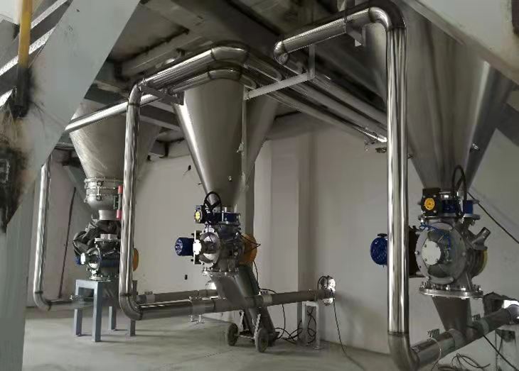
Weighing module
Weighing modules are used for measuring and storing materials. The effective volume of the weighing module is usually selected according to the volume of the material which is 3~5arin the whole weighing process under the maximum discharge flow. The feeding time of the feeding device (time without weight control and adjustment) is about 1O% of the total weighing process. The dosing module is equipped with a load cell for converting the weight of the material into an electrical signal for PLC control.
Discharge device
The discharge device is used to discharge the material in the container of the weighing module. According to the characteristics of the conveyed material and the different environments, continuous conveying equipments such as screw conveyor and belt conveyor can be used, and the frequency conversion technology is used to change the rotational speed of the motor to regulate the feeding speed.
Control system design
The loss-in-weight control system adopts Siemens S7-300/400 series PLC with industrial Ethernet interface, which can be freely expanded when the loss-in-weight control task increases. The digital input and output modules adopt 16-point 24VI~ SM32 and SM321, the analog weight signal input adopts 8-point 16-bit SM311, the temperature signal input adopts 8-point 16-bit SM331, and the analog speed signal output adopts 8-point 12-bit SM332.
The upper computer workstation adopts three Lenovo commercial machines, and it realizes MPI communication with PLC through CP561 communication card. The human-machine interface (HMI) adopts SIEMENS WinCC, which has a complete operation interface and can record various data and alarm display in real time. Users can choose the number of software points and functions according to the size of the system.
Loss-in-weight Scale Commissioning and Precautions
Commissioning of loss-in-weight scales
Loss-in-weight scales are not affected by the mechanical changes of the scale body and feeding mechanism in principle, and have the characteristics of both static and dynamic scales, therefore, static and dynamic commissioning must be carried out before use.
1, static commissioning steps. According to the maximum range of the scale labeling, prepare the appropriate weights.
2. Zero adjustment: When the scale is empty, adjust the zero parameter and magnification on the load cell, and adjust the weighing display to zero on the host computer.
3、Maximum range adjustment: Add weights one by one to the full range, observe whether the display on the upper computer calibration screen is the same as the weights added to the scale, and then click on the calibration screen to calibrate the full scale.
4、If there is any deviation, remove all the weights, observe whether the display on the calibration screen is zero, and then click Calibrate Zero.
5. Repeat steps 3 and 4 until the requirement is met.
Dynamic calibration steps
Dynamic calibration requires the preparation of a stopwatch and a 30~50kg electronic scale, according to the requirements of the recipe for the corresponding loss-in-weight scale for stand-alone calibration, the flow of recorded data and the microcomputer set the flow rate to compare, and observe whether it is within the set range.
Loss-in-weight scales design considerations
Loss-in-weight scales are characterized by static and dynamic scales. Considering the factor of precision, it is required in the design of the system.
(1) the correct range of conveying rate, generally the best actual working range of 30 ~ 80 of the rated conveying capacity, if the use of AC speed control, for the strain frequency of 15 ~ 40Hz, so as to ensure that the adjustment range is wide.
(2) load cell range selection is appropriate, the maximum volume of the weighing bucket according to the design of the maximum flow operation, to ensure stable operation for 3min, the formula is: Weight = FIo a (kg/min) - 80/3 (min) the actual design of the load cell range using the system can be in the range of 60 ~ 80, theoretically, the wider the range of signal changes, the higher the accuracy of the system. Must reserve a certain margin for the sensor to avoid overfilling, beyond the sensor range, damage to the sensor.
(3) The feeding system is to calculate the actual flow rate by differential reduction, which puts high requirements on the stability of the weight signal. Therefore, the following points should be noted.
1, good grounding to prevent interference, signal cable and power cable must be separated and placed in different cable grooves.
2, the load cell shielding line and signal line, ground line, etc. can not form a loop, otherwise it will cause the instrument input signal instability.
3、Weighing transmitter should be installed in the field as much as possible in order to reduce the signal interference.
Application Trend
In order to be more adaptable to the needs of dynamic and accurate measurement, it is crucial to use the load cell as the input of the system in the weighing system. At present, most of the traditional analog load cells are used in our country, whose signals are susceptible to radio frequency interference, and the cable transmission distance is usually within 10m. With the rapid development of electronic control technology, loss-in-weight scales through the use of new technologies to continuously improve the accuracy of measurement, the core of this new technology for the application of digital load cells, the advantages of which is to achieve "self-calibration", "self-diagnosis", and high resolution. Therefore, the application of digital load cell in weighing system will be a trend.