

 2020.01.12


Summary:Material batching system is a metering device of material quantitative feeding system based on PID control algorithm of PLC. The structure of the control system and the hardware composition of PLC are expounded. According to the technical requirements of the technological process, the actual situation of the quantitative feeding process of industrial materials is systematically considered from the hardware configuration of the control system to the design of the application program. The application results show that the system has stable performance, reliable operation, intuitive and flexible man-machine interface, and all the functions realized by the control system meet the technological requirements, and good application results have been achieved.
In the field of production, the proportioning accuracy between various raw materials has an important impact on the stability of the production process and the quality and yield of the products. Quantitative batching and feeding system has been widely used in cement and building materials, metallurgy and chemical industry, electric power and coal and other industries powder liquid continuous transmission flow measurement and quantitative feeding of industrial links. For example, the quantitative feeding and conveying of coal powder in cement plant kiln is a typical example, and the stability and uniformity in the feeding process are the main factors affecting the metering accuracy. Because of its wide range of uses, to improve the degree of automation of the feeding system has an important practical significance. The material quantitative feeding system is a dosage system metering device designed according to the development status and trend of intelligent dosage system at home and abroad, combining with the specific requirements put forward by MDI tannery enterprises; it adopts the programmable controller as the core of the whole control system, which is characterized by the advanced principle, simple structure, uniform and reliable dosage feeding, and accurate measurement.
1 system structure and design
Programmable controller in mechatronics products in a wide range of applications, its main features are: reliable, direct input and output connection with industrial field signals, flexible combinations, easy programming, simple installation, easy maintenance, rapid operation, for the relay logic control can not be expected. The measurement device control objects and parameters, harsh working conditions, and requires a certain management functions, in order to improve the reliability of the system, easy to maintain, it is proposed to use the programmable controller as the core, touch screen computer as an interactive interface, with a variety of input and output special modules and special signal conditioning circuits to form a complete control system.
1.1 System measurement and control time sequence
System measurement and control time sequence in the lowest point of the material level, the control output loading generation instruction, the loading valve accepts the open instruction to open, the system enters the volume feeding period. After a time delay, the charging valve all open, and issued charging valve fully open feedback signal to the control system, after a set time delay, the sulfurized air open, the system enters the rapid charging phase. When the material is added to the highest point of the material level, the weighing control system detects the hopper full of material and outputs the loading valve closing signal, the loading valve accepts the instruction to start closing, the system runs to the loading valve full shut-off point, outputs the butterfly valve closing signal, the system ends the loading process, and enters into the discharging stage. After a period of stabilization time the system runs to the weight feeding start point, at this time the volume feeding is over, the system enters into the weight feeding stage, the measurement and control cycle begins, continues to the next given level of the lowest level of material, the system sends out the instruction of loading control. This cycle alternates feeding operations.
1.2 Measuring device dosage control system
The dosing control system consists of two parts: the upper computer system and the lower computer system.
1.2.1 Upper computer system
The touch screen computer as the upper computer mainly realizes the functions of supervisory control level and management level. It processes the user's input commands and displays the operation information in time. Since the touch screen computer comes with the function of communicating with PLC without writing a special communication program, it is very convenient to use as long as the interface is well designed.
1.2.2 Lower computer system
The lower computer system is mainly composed of the following parts:
(1) Programmable controller. The programmable controller is the control center of the lower computer system, on the one hand, it is responsible for the communication function with the upper computer; on the other hand, it controls the actions of the actuators according to the instructions of the upper computer. Considering the load condition of the system and the need of control, G11-5.5KW inverter of Fuji is selected. The adapted motor is 5.5kW, and the control mode is flexible PWM (V/F control). The output control of the running frequency is carried out by an analog quantity (0 a 10V), and this analog quantity value is given by the 2D/A module of PLC.
(2) Receive conditioning circuit. It receives the differential signals transmitted from the field, converts them into switching signals and sends them to the high-speed counter of the PLC for counting.
(3) Speed detection analog-to-digital conversion circuit. Converts the speed of motor operation into digital quantity to be sent to PLC.
(4) Electrical parameter detection function module. Convert the current, power and efficiency of the motor into digital quantities and interface them to the PLC and the host computer.
(5) Digital-to-analog conversion function module. Convert the speed control data calculated by PLC into analog signals and send them to the frequency converter to control the speed of the downstream motor, so as to achieve the purpose of controlling the amount of feeding.
(6) Weighing module. The weighing sensor is a traditional resistance strain pressure sensor, which adopts ET I3 type metering module. However, its output range is only 0-21.6mV (supply voltage DC 12V), the output resistance of 351 ohms, can not be directly sampled for A/D conversion. AD623 chip is used to amplify this signal 50 times.
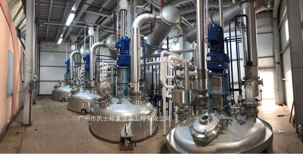
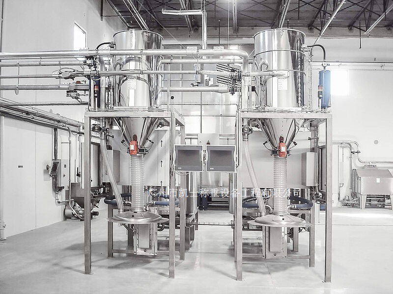
1.3 Mechanical body and electromechanical interface
The field part is mainly a mechatronic actuator, which mainly includes elements such as mechanical body, power part, measurement and sensing part, actuator, driving part, etc., and each element is connected through the interface.
(1) Filling solenoid valve and butterfly valve. By the PLC output relay closure, closure, to control the feeding solenoid valve on and off, through the actuator to realize the hopper in the material gap automatically added.
(2) Measuring and sensing part. The weight information needed in the system operation is detected and turned into an electric signal, which is processed by the signal conditioning circuit and sent to the control room as a differential signal.
(3) Powder conveying screw and driving mechanism. It is the main actuator of the system, through its operation, material feeding is realized. The spiral spindle is powered by an inverter motor, and the spindle is dragged to run after deceleration through a first-class cycloid reducer, and the running speed of the inverter motor is controlled by the frequency converter.
(4) Powder compaction and driving mechanism. It is the main actuator of the system material and realizes the compaction of the material through its operation. The mechanism is powered by an electric motor, and drags the compaction mechanism to run after deceleration through a secondary cycloid reducer.
2 programmable controller PID algorithm
PID control has the characteristics of simple principle, easy to use, adaptability, etc. The metering device uses the control calculation ability of PLC to replace the analog regulator, and directly through the digital operation, so that the regulated quantity is maintained at a given value.
Many of the parameters of the PID instruction can be set or set by the user according to their own needs, from the beginning of the control to the PID cycle to achieve the device control requirements of the difficulty is to find a good starting point for control. It is important to ensure safe operation when adjusting the PID value to avoid damage to the device. Pre-adjustments can be made to the FX2N series PLCs to quickly assign initial values to the PID control process. A simple way to do this is to change a fixed percentage of the parameter value at a time, such as increasing or decreasing it by 10% each time.
3 Conclusion
Measuring device according to the principles of ergonomics for measuring device interface design, the use of color LCD and special cabinet design to ensure the convenience of operation and correct; PLC for the control center, screw conveyor and other materials for the propellant, with the relevant implementation of the drive components, so that the system can run automatically. The whole system feeding amount for closed-loop control, the use of object-oriented programming methods, and process-oriented programming methods combined with optimized interface and process design, can be convenient for functional expansion; and has a remote communication interface, when needed, can be composed of a network to adapt to the needs of the modernization of the plant, the dosage accuracy of 0.5% level. The device has been applied in the enterprise, and the operation condition is good.