

 2025.05.05


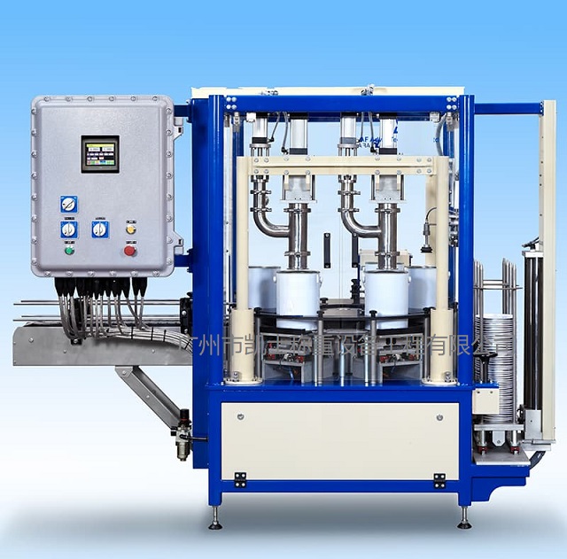
Summary:The liquid filling machine adopts high-precision electronic weighing technology to achieve high-precision dynamic measurement and filling of liquid media. Its measurement accuracy is not affected by factors such as pressure, temperature, bubbles, etc.
Automatic filling machine is embedded way based on ARM industrial control and data acquisition filling system, filling system has a very small C language link library, completely contains the data engine function, without additional settings can be embedded in other programs, provides most of the support for SQL92, including tables, indexes, triggers and views. The file format of the database is cross-platform and can be ported between 32-bit and 64-bit systems, including preset parameter information, basic equipment information, real-time measurement and control information and fault information, etc., in which the preset parameter information and basic equipment information are set up and recorded by the user, and the real-time measurement and control information and fault information are captured by the weighing module and stored in the embedded database through the data processing program (borrowed from the SOLiteC/C++ interface). The application program can obtain and update the status of each control point in real time through the processing of the database records and issue commands to achieve the purpose of real-time monitoring and control.
Automatic filling machine using C language written in open source embedded ACID associative database management system that can support Windows/Linux/Uni and other mainstream operating systems, at the same time can be combined with many program languages. SOLite is also very robust its creators conservatively estimate that SOLite can handle the daily burden of up to 10,000 hits on the Web site, and SOLite can sometimes be used to handle up to 10,000 hits on the Web site, and SOLite can sometimes be used to handle up to 10,000 hits on the Web site. site, and SOLite can sometimes handle 10 times the load of the above figures, real-time access to the production line filling data (production time, filling weight, recording time), and store the data into the database, and then manage the data. According to the production record data to determine whether the filling production meets the requirements, so all users, including the administrator user can only modify the data of the qualification mark and note information, statisticians and administrators can query the data by day, month, year and can be printed, because the SOLIte database is in the form of a file to store the data, so the backup of the database can be used to copy the database file Since the SOLIte database stores data in files, database backup can be realized by copying the database files to a new directory.
The weighing and filling machine adopts an image tracking system and fills the image with a display device that can fully reflect the three-dimensional information with a sense of depth and hierarchy. It can intuitively feel the distance and distribution of the objects in the image, so that it can more directly obtain effective spatial information, which is realized by the movement of the filling valve controlled by the movement of the grating by the stepping motor. Can support Windows/Linux/Uni and other major operating systems, at the same time can be combined with a number of program languages, SOLite is also very robust its creators conservatively estimate that SOLite can handle the daily burden of up to 10,000 hits on the Web site, and SOLite can sometimes deal with 10 times the load of the above figures, real-time access to the Filling data on the production line (production time, filling weight, recording time), and store the data in a database, and then manage the data. According to the production record data to determine whether the filling production meets the requirements, so all users, including the administrator user can only modify the data of the qualification mark and note information, statisticians and administrators can query the data by day, month, year and can be printed, because the SOLIte database is in the form of a file to store the data, so the backup of the database can be achieved by copying the database file to a new directory.
Main process
(1) Connect the power supply, the weighing controller self-check and zero;
(2) Place the bottle on the scale and start filling;
(3) The filling nozzle starts to descend, open the filling valve and start to fill the material quickly;
(4) When the weight of the material reaches the set weight of slow filling, start to switch to slow filling;
(5) When the material weight reaches the set target weight, close the filling valve and raise the filling nozzle again;
(6) One filling cycle is completed.
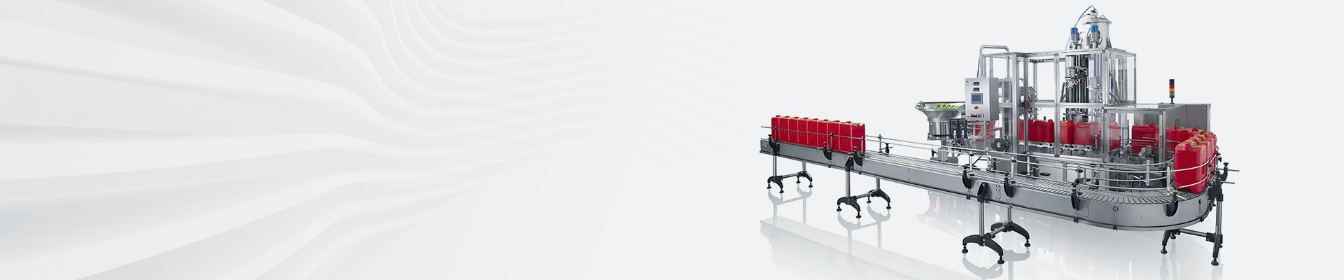
Technical requirements
(1) Filling weight: 5~50kg;
(2) Production capacity: 80~260 barrels/h;
(3) Weighing error: ≤0.2%;
(4) Power supply: AC220V±10%;
(5) Working temperature: -5℃-50℃;
(6) Ambient humidity: ≤90% relative humidity (no condensation).
(7) Multi-stage speed feeding mode, improve efficiency.
(8) Adopt vacuum suction back to ensure that the filling residual liquid will not pollute the packaging container.